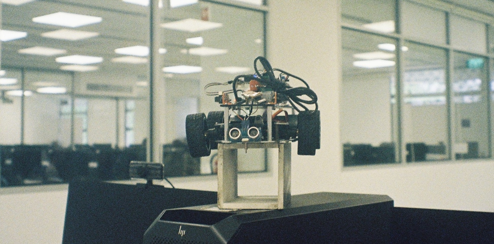
 A picture of our robot car, taken in film :)
Introduction
Greetings! Welcome to the MDP space~ I was a student who took MDP back in AY24/25 Sem 2. Things might have changed while you’re reading this blog. Maybe there is no longer a robot car for MDP but other forms instead, maybe something has changed in the tasks given, or maybe we are no longer using STM32 while building the robot. This blog doesn’t aim to give you very comprehensive or ready-to-be-copied code, but rather focuses on our experiences in MDP, things that are not covered in materials, and some self-learning websites that we found very helpful. In this blog, we will also introduce the different tasks you can work on (Raspi, Image Recognition, Hardware, Algorithm, Video Making, etc.), including some good-to-have prerequisites in case you’re wondering which task to choose.
Job Scopes
Raspberry Pi
🎯 Main Objective
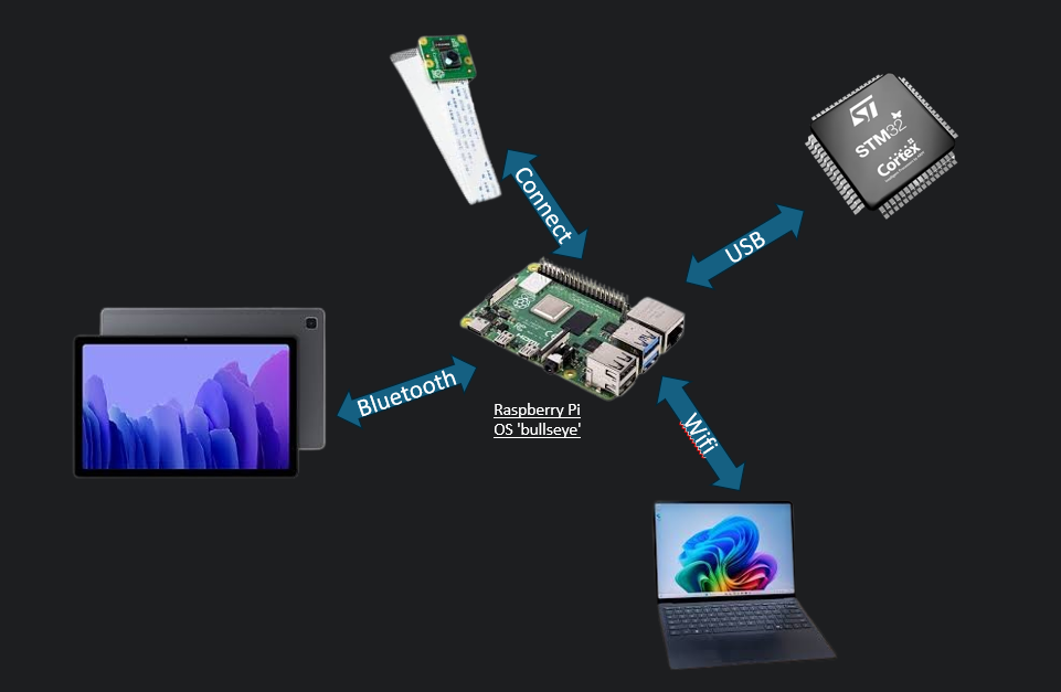
Raspberry Pi is the central hub for all the communications between different devices.
If:
❓Android wants to tell other devices that we are starting the task? Through Raspi.
❓PiCamera wants to send Android the picture? Through Raspi.
❓Algorithm wants to update Android Robot position? Through Raspi.
❓STM wants to receive commands in order to move? Through Raspi.
As the central hub for everything, sometimes we feel that the person responsible for Raspi is the babysitter for the team. Whenever the children (the devices) want to communicate with each other, we act as the mediator, relaying the messages.
📚 Good to have basics
Linux, Python
🔗 Resources
⚡ Interesting Problems
- SCP for the win!
I have heard that there are people who copy character by character when they are updating file in Raspi. Let’s not do that…. Just use secure copy command:
scp [OPTIONS] [[user@]src_host:]file1 [[user@]dest_host:]file2
Alternatively, you can use vscode plugin to edit code directly:
 2. The guide -
 RPI-InfraSetup-v5(05JAug2024).pdf is not applicable to Raspi Version Bookworm, only works until Bullseye ._. due to Network Manager Update.
By default, Bookworm uses Network Manager (nm) for network configuration. If you’re confident in it and are always up for a challenge then please do go ahead! If you feel that you need to follow the guide to be able to understand network configuration, you should get Bullseye :)
3. You can make PiCamera works! But using PiCamera 2 saves a lot of time.
If your code is already based on PiCamera, and you want to make it work on Raspi 4:
sudo raspi-config
# Navigate to: Interface Options > Legacy Camera > Enable
To check if camera is detected:
vcgencmd get_camera
Edit /boot/config.text to load correct hardware configuration when booting:
sudo nano /boot/config.txt

# Enable camera
camera_auto_detect=1
start_x=1
gpu_mem=128

# For legacy camera support
dtoverlay=vc4-kms-v3d
dtparam=spi=on
dtparam=i2c_arm=on
- Set up Raspi in your hall / house, as NTU server allocates RPI to different subnet.
Main gist is get a charger to charge your Raspi, connect Raspi to your router through ethernet cable, then use hdmi to connect a monitor, lastly followed by connecting your mouse and keyboard. And then ¡viola!, you’re good to go! - C is faster, Python has GIL, but we have 4 cores :)
Students might debate which is better for the MDP context: C multithreading or Python multiprocessing.In my recommendation, I would suggest Python multiprocessing.This is because the Raspi 4 has 4 cores, which means Python’s Global Interpreter Lock (GIL) won’t cause problems in execution.
When you use Python’s multiprocessing library, you can have multiple processes running in your Python file, and each process will be assigned to whichever Raspi core is available. One could argue that having more than 4 processes creates higher memory pressure, inter-process communication and overhead due to GIL limitations. However, GIL only affects the thread level, not the process level - each Python process has its own interpreter and can truly run in parallel.
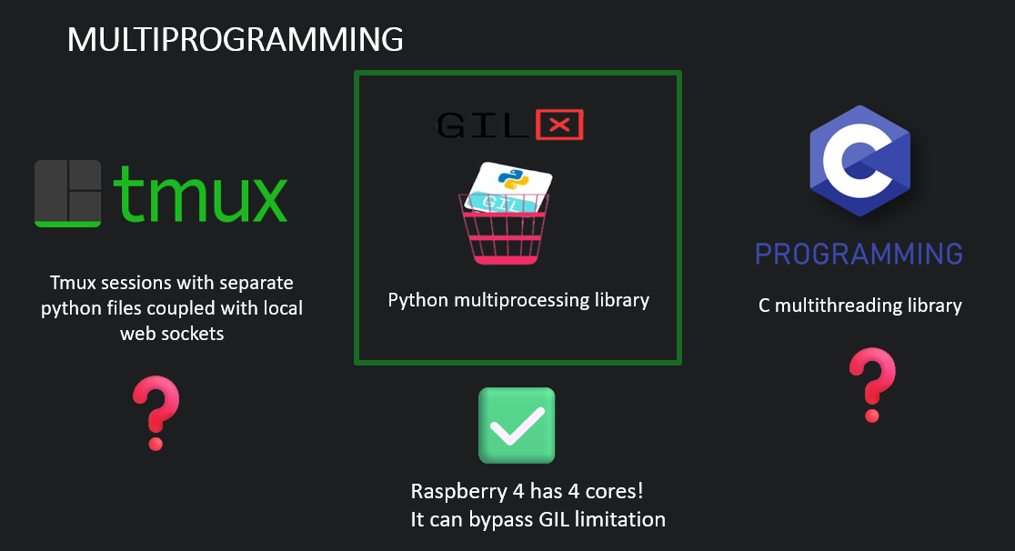 As shown in the diagram above, there are several approaches to multiprogramming on Raspberry Pi. Another alternative is using tmux to run different Python files in separate sessions, but my friend found that this sometimes caused the terminal to crash, so it’s not highly recommended. While C multithreading is also an option, Python multiprocessing leverages the Raspberry Pi 4’s quad-core architecture most effectively. When you’re using Python processes, their execution is managed by your operating system scheduler. If you have more processes than CPU cores, the extra processes wait in the background to be scheduled, but the core processes can still run simultaneously without GIL interference.
Image Recognition
🎯 Main Objective
Both tasks in MDP require training models to recognize characters. For the first task, you will typically receive 5-7 images to be recognized. You must train a model to distinguish between these characters, then host it on your local laptop. For the second task, you need to distinguish the left and right arrow. When the PiCamera sends a picture to the Raspberry Pi, the Raspberry Pi forwards the picture to your local PC to run inference on it. The result is then sent back to the Raspberry Pi, and finally, the Raspberry Pi sends the Image ID to the Android device for display.
📚 Good to have basics
nvidia-smi, rocm-smi, tmux or screen
If you’re thinking of taking this task, I strongly suggest that you ensure access to a GPU. (Because I know someone who used Roboflow to train a Yolo model and that person spent 4 days on CPU Job…) RTX 3060 is good enough :)
🔗 Resources
Google Search Roboflow NTU MDP
⚡ Interesting Problems
- Roboflow Image Augmentation Problem
My Recipe:Category Setting Value Preprocessing Auto-Orient Applied Resize Stretch to 640x640 Auto-Adjust Contrast Using Histogram Equalization Augmentations Outputs per training example 3 Grayscale Apply to 15% of images Saturation Between -33% and +33% Brightness Between -22% and +22% Blur Up to 1.3px Noise Up to 0.34% of pixels
Do be aware that you shouldn't apply Image Augmentation Step such as Flip or 90 degree Rotate because it will mess up with the arrow labels.
- If you want the training to be faster, you should maximize GPU memory utilization by increasing the batch size.
What is Batch Size? Batch size refers to the number of training examples your model processes simultaneously in one forward pass. For example:
- Batch size = 32: Your model looks at 32 images at once
- Batch size = 64: Your model looks at 64 images at once
Why Does Larger Batch Size = Faster Training?
- Parallel Processing: GPUs are designed to handle many calculations simultaneously. A larger batch size means you’re utilizing more of your GPU’s parallel processing power, making each training step more efficient.
- Fewer Training Steps: If you have 1000 training images:
- Batch size 10 = 100 steps per epoch
- Batch size 50 = 20 steps per epoch
Fewer steps mean less overhead from data loading and memory transfers.
Increase the batch size until you receive the CUDA Out of Memory Error. Then you reduce the batch size slightly before encountering the error.
- Can I use CNN instead and not use Roboflow?
Definitely! Though I have to be frank that using Roboflow saved me a lot of time. Using Roboflow will enable us to download the dataset to our local compute with one line of python command. Then we can useUltralyticslibrary to fine-tune the model in less than 10 lines of Python. Another benefits of using the Yolo model is it will out put the coordinates for the boudaries. So, you can use it directly to draw the border.
This is the function that I have created to extract the borders’ coordinates.
def detect(image):
    image_height, image_width = image.shape[:2]
    blob = cv2.dnn.blobFromImage(image, 1/255.0, (640, 640), swapRB=True)
    net.setInput(blob)
    outputs = net.forward()[0]

    class_scores = outputs[4:, :]
    confidence = np.max(class_scores)
    class_id = np.argmax(np.max(class_scores, axis=1))

    box_index = np.argmax(class_scores[class_id])
    box_location = outputs[:4, box_index]

    x, y, w, h = box_location
    x = int(x * image_width / 640)
    y = int(y * image_height / 640)
    w = int(w * image_width / 640)
    h = int(h * image_height / 640)
    cv2.rectangle(image, (x - w, y - h), (x + w, y + h), (0, 255, 0), 2)

    label = f'{class_names[class_id]} {confidence:.2f}'
    cv2.putText(image, label, (x, y), cv2.FONT_HERSHEY_SIMPLEX, 0.5, (0, 255, 0), 2)
    timestamp = int(time.time())
    cv2.imwrite(f'test_result_{timestamp}.jpg', image)

    return class_names[class_id], float(confidence)
- My model is running quite slow on my laptop, what can I do?
Convert the format toONNX, optimized runtime and better utilization of CPU SIMD.
Algorithm
🎯 Main Objective
On the actual day of the Task 1 examination, the map and obstacle coordinates are unknown. The professors and TAs will also ensure that they separate the lab into examination and waiting areas, so that groups in the later sequences will not be able to memorize the map. You also have to leave your laptop and robot car on the table once the examination starts for the first group.
Since the map is unknown, once it’s your group’s sequence and you’re invited to the lab, you will have 2 minutes to set up. During these 2 minutes, you have to plot the obstacle coordinates on the Android map, then send them to Raspi, and Raspi will send them to the laptop that is hosting the algorithm server (preferably also hosting the Image Recognition Model Server on the same laptop). Then, the algorithm server will compute the best path and send the optimal set of commands to Raspi, which will send the commands one by one to STM. After STM performs each action, it will send an acknowledgement to Raspi, and Raspi will notify Android to update the current robot position.
So to summarize, the main objective of the algorithm is to compute the best path so that STM knows what to do~
📚 Good to have basics
Python, Flask
🔗 Resources
⚡ Interesting Problems
- Camera position at the side of the car?
This is a potential optimization that is worth exploring (if you have time). Instead of requiring the robot to stop and turn to face each obstacle directly, we could mount the camera on the side of the robot. This way, the robot could capture images of obstacles while moving parallel to them, eliminating the need to waste time turning 90 degrees to face each obstacle directly. - In place 90 degree turn?
Many students will refer to seniors’ GitHub code while writing their own code. Just a reminder that a few years back, our seniors were using different hardware where their robot could perform in-place 90-degree turns. Bear in mind that our current robot can’t do that - we have to account for the turning radius while computing the best path. When your algorithm is doing path planning, make sure that your algorithm
- account for turning radius and distance
- Writes boundary conditions according to what you want the robot to do (for example, maybe the robot doesn’t have to face the obstacles directly in a straight line; if the coordinates are ±1 grid unit away, you can allow the robot to stop and take a picture too)
- will be able to interact with flash server so you can communicate with Raspi
STM32
🎯 Main Objective
Moving the robot ._.
I must declare that this section is more tailored to computer science students who are tasked to work on STM. I will be writing about my experience learning STM32 from scratch as a Computer Science student. So I apologize if you’re a CE student and you find this basic.
Learning STM32 as a Computer Science student might sound scary at first, but I think the learning curve is mainly about knowing how to use STM32CubeIDE and understanding actual pin configurations.
This main.c file is where you will do most of your coding: Note that you should write your code within the declared USER CODE sections. If you write it outside of these sections, your code will be deleted every time you change and save your MDP.ioc file.
Here’s the main.c:
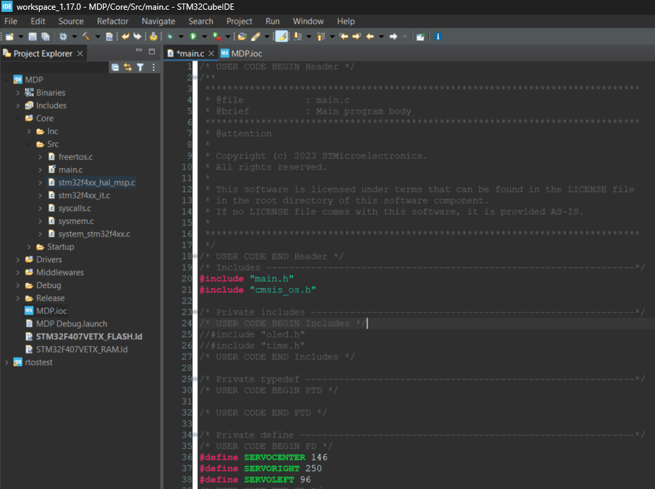 Here’s the
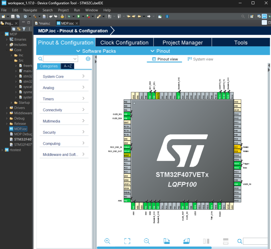
 .ioc file:
📚 Good to have basics
STM32CubeIDE
🔗 Resources
⚡ Interesting Problems
What is the .ioc file?
The .ioc file is a configuration file created by STM32CubeMX (integrated into STM32CubeIDE). It’s a graphical interface where you:
- Configure microcontroller pins (GPIO, UART, SPI, etc.)
- Set up peripherals (timers, ADC, PWM, etc.)
- Configure clock settings and system parameters How does it generate main.c?
When you save the .ioc file, STM32CubeMX automatically generates C code including:
- main.c - Main application file
- Hardware Abstraction Layer (HAL) initialization code
- Peripheral configuration functions
- System clock configuration
Key Relationship:
.ioc file = Visual configuration (what you want) Generated main.c = Actual C code implementation (how to do it)
Critical Rule 1: STM32CubeIDE regenerates parts of main.c every time you modify and save the .ioc file. That's why you must write your custom code only within the designated "USER CODE" sections - these sections are preserved during regeneration.
Critical Rule 2: You must create an account in STM32CubeIDE before you can auto-generate the code. I once spent quite some time trying to debug why I couldn't auto-generate the code even though there were no warnings, and it turns out it was an account issue causing the problem.
📟Hardware Configuration Constants
Servo Steering Constants
#define SERVOCENTER 146
#define SERVORIGHT 250
#define SERVOLEFT 96
| Constant | Value | Steering Angle | Usage |
|---|---|---|---|
SERVOCENTER |
146 | 0° (straight) | Default position, straight-line movement |
SERVORIGHT |
250 | ~45° right | Maximum right turn for tight corners |
SERVOLEFT |
96 | ~45° left | Maximum left turn for tight corners |
PWM Timer Assignments
// From timer initialization
htim1.Init.Period = 1000;    // Servo control (TIM1_CH4)
htim8.Init.Period = 7199;    // Motor control (TIM8_CH1, TIM8_CH2)
| Timer | Channel | Purpose | Max Value | Resolution |
|---|---|---|---|---|
TIM1_CH4 |
4 | Servo steering | 1000 | 1000 steps |
TIM8_CH1 |
1 | Left motor PWM | 7199 | 7200 steps |
TIM8_CH2 |
2 | Right motor PWM | 7199 | 7200 steps |
Movement Control Variables
PWM Control Variables
uint16_t pwmVal_servo = SERVOCENTER;  // Servo steering PWM
uint16_t pwmVal_R = 0;                // Right motor PWM
uint16_t pwmVal_L = 0;                // Left motor PWM
| Variable | Range | Default | Purpose | Hardware Connection |
|---|---|---|---|---|
pwmVal_servo |
96-250 | 146 | Front wheel steering angle | TIM1_CH4 → Servo motor |
pwmVal_R |
0-7199 | 0 | Right wheel speed control | TIM8_CH2 → Right motor driver |
pwmVal_L |
0-7199 | 0 | Left wheel speed control | TIM8_CH1 → Left motor driver |
Movement State Variables
int times_acceptable = 0;   // PID stability counter
int e_brake = 0;           // Emergency brake flag
| Variable | Type | Purpose | Trigger Conditions |
|---|---|---|---|
times_acceptable |
int | Counts consecutive “good” PID iterations | Increments when error < 2, resets on large error |
e_brake |
int | Emergency stop flag | Set to 1 to immediately halt all motors |
Turning Movement
void moveCarRight(double angle) {
    pwmVal_servo = SERVORIGHT;          // Set maximum right steering
    osDelay(450);                       // Allow servo to settle
    target_angle -= angle;              // Update target orientation

    while (finishCheck());              // Wait until turn complete
}
Turn Control Strategy:
- Servo positioning: Set to maximum turn angle (96° or 250°)
- Differential drive: Inner wheel slower, outer wheel faster
- Gyroscope feedback: Uses
target_anglevstotal_angleerror - Completion: Based on angular error tolerance
PID Speed Mapping
int PID_Control(int error, int right) {
    error = abs(error);
    if (error > 2000)      return 2050;    // Maximum speed
    else if (error > 500)  return 1800;    // High speed
    else if (error > 200)  return 1400;    // Medium speed
    else if (error > 100)  return 1000;    // Low speed
    else if (error > 2)    return 500;     // Fine adjustment
    else                   return 0;       // Stop (acceptable error)
}
| Error Range (ticks) | PWM Output | Speed % | Use Case |
|---|---|---|---|
| > 2000 | 2050 | ~28% | Large distance corrections |
| 500-2000 | 1800 | ~25% | Moderate distance corrections |
| 200-500 | 1400 | ~19% | Small distance corrections |
| 100-200 | 1000 | ~14% | Fine positioning |
| 2-100 | 500 | ~7% | Very fine positioning |
| < 2 | 0 | 0% | Target reached |
Emergency Stop Conditions:
- Command completion (
times_acceptable > 20) - System reset command (
GYROR) - Manual override through
e_brakeflag
Video
🎯 Main Objective
The goal is to show the learning progress throughout the weeks. It’s good to have a storyline, but essentially what professors are looking for is growth and teamwork. Aesthetics aren’t as important as you might think.
📚 Good to have basics
GPU (Optional), Video editing skills, knowing where to get soundtracks, and how to trim videos, etc.
🔗 Resources
DaVinci Resolve
Personally I am a fan of Davinci Resolve. Because it’s completely free and offers many good features that many paid editors charge hundreds of dollars for. For MDP project, you will mainly use the Edit and Fairlight (Audio) pages. The interface might seem overwhelming at first, but focus on basic editing, transitions, and audio mixing (if you have time). That’s all you need for a compelling project showcase.
⚡ Interesting Problems
- Remember to take videos and images throughout the weeks, don’t wait until the last minute.
- When sharing video project files with your teammates (assuming more than one person is working on video editing), remember to also send the source video files. Otherwise, the project files that your teammates open in DaVinci Resolve will display a lot of missing video file warnings in red.
Quiz
🎯 Main Objective
This is an individual task. Be aware that if you choose only either Raspberry Pi or Image Recognition, you will still need to take both (Raspberry Pi + Image Recognition) in the actual quiz. For this section, I can only speak about Raspberry Pi + Image Recognition since that was the test I took.
📚 Good to have basics
Having taken SC4001 Neural Networks and Deep Learning is helpful, especially if you’re the person actually setting up the Raspberry Pi — then there should be no problem.
I remember attending the SC4001 lecture the day before the Raspberry Pi quiz, where I learned how to calculate the number of parameters for CNN layers, and it actually appeared in the MDP quiz! I was quite lucky :)
🔗 Resources
Check with anyone with SC4001 CNN Notes.
⚡ Interesting Problems
NULL
Very important reminder, on how I failed my task 2.
No one told me this before, but since you’re reading this, I hope you can avoid my mistake. We failed Task 2. Not because we couldn’t code anything, not because of hardware failure, but simply because the ground in the lab has different friction compared to North Spine TR where we did most of our testing. The TR floor in North Spine is slippery, so when we were tuning the angle, speed, parking position, and everything else in TR, we tended to use smaller turning angles because the car would sometimes tip over. Things went well the night before Task 2 (we pulled an all-nighter, slept in TR, and thought everything would be okay). But when we woke up and went to the lab for one last test before the 8:30am exam time, we realized our car always hit the wall and significantly “under-turned” on the lab floor. We could tell it wasn’t going well for the first run, and I even had to code the STM on the spot to adjust the angle and make it into the parking spot for our second try. While my second attempt fixed most of the value errors, it unfortunately failed at the last angle and couldn’t park in the parking spot.
The lesson is: do your testing in the actual exam venue. Maybe prepare two sets of configurations/angles as well, just in case you are unsure whether you will be testing indoors or outdoors.
Closing
Thank you for reading through this guide. I sincerely appreciate your time in reading my thoughts and I hope you succeed in whichever path you choose to pursue. I understand that MDP can be quite stressful for many students, particularly if you find yourself in a group that isn’t functioning well together. I want to take this opportunity to reassure you that being part of a struggling group doesn’t reflect poorly on you as an individual. Sometimes it’s simply a matter of being matched with people who have different priorities or approaches to the project. My mentor once shared some wisdom with me: “When you find yourself carrying most of the workload in a group, it might simply mean you’re ready for a more collaborative environment where everyone shares the same level of commitment and goals.” Finally, if you ever need support in managing the emotional challenges that can come with group projects, university counselling centre is always ready, there’s absolutely nothing to be ashamed of in seeking support when you need it :D
Also, credit to Danxu and Yoong Ken for helping me proofread this blog :)