Scaling Distributed GEMM on Cerebras Wafer-Scale Engine
In Large Language Model (LLM), the fundamental operations of transformer architecture are attention and multi-layer perceptron computation, both of which are built on a massive amount of GEMM (General Matrix Multiply) and GEMV (General Matrix-Vector Multiplication). During inference, the decoding step (specifically GEMV) is memory-bandwidth bound due to the LLM autoregressive nature. (i.e. the GPU, such as NVIDIA’s accelerator, spends most of its time loading data into the compute unit for a relatively little computation, which computes one new token per step.) To address this issue, research has been attempting to transform this memory-bound workload to compute-bound by converting GEMV into GEMM operation through batching. However, memory movement is still relatively expensive. This observation of memory movement as the primary bottleneck, has encouraged companies like Cerebras to adopt a spatial dataflow architecture, in which compute units form a processing grid, enabling them to send data to one another at lower memory-transfer costs, thus addressing memory bound application from a hardware approach.
Source: Cerebras SDK Documentation
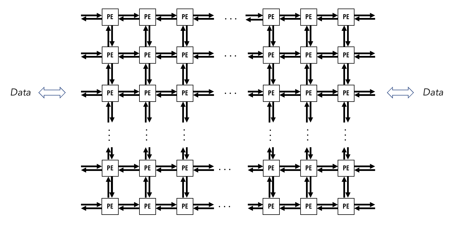
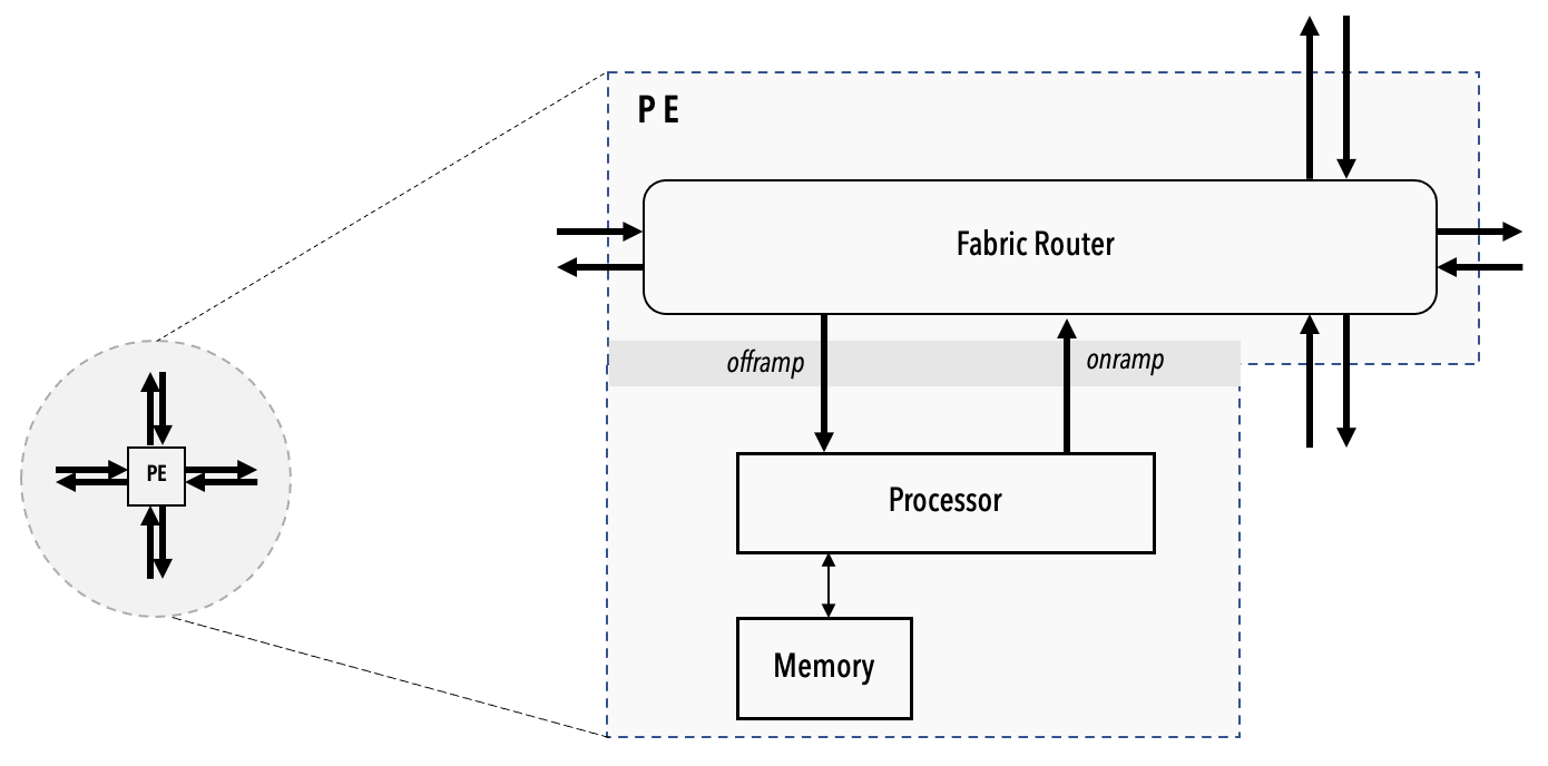
In the example of Cerebras Wafer-Scale Engine (https://sdk.cerebras.net/computing-with-cerebras), each engine consists of Processing Grid, each Grid consists of many Processing Element (PE), and each PE consists of the compute engine processor (CE). Other than CE, each PE also has a router connecting to 4 neighbours (North, South, East, West), and a local PE memory. The processor grids resemble the distributed memory architecture in traditional parallel computing, where each of the PEs can’t access their neighbour’s local PE memory, but they can execute point-to-point send and receive of data among neighbours, just like the Message Passing Interface, a protocol in multinode parallel computing.
Source: Cerebras SDK Documentation
This emergence of 2D processor grids on the Cerebras accelerator has ignited another wave of interest in traditional parallel computing, evidenced by the fact that Cerebras uses the traditional SUMMA algorithm (a distributed GEMM algorithm borrowed from traditional parallel computing) to compute GEMM on the Wafer-Scale Engine. However, the direct adoption of SUMMA on Cerebras Wafer-Scale Engine is suboptimal because it missed out hardware-specific optimisation opportunities. For example, SUMMA communication latency per step scales with a complexity of O(αP), where α is a constant hop latency, and P is the height/width of a PxP processor grid. And since there are P steps in total, the overall communication latency scales as O(αP^2). To solve this issue, a team from the University of Edinburgh invented MeshGEMM, a variant of the Cannon algorithm (another distributed GEMM algorithm from traditional parallel computing), reducing the communication latency per step to O(α). Their published work, WaferLLM, claims to improve GEMM computation by 2-3x over SUMMA.

Source: SUMMA Algorithm from UIUC Lecture Note
Our top-level objective in this project is to determine whether distributed GEMM algorithms originally designed for traditional parallel computing retain their theoretical properties when implemented in scale on the Cerebras Wafer-Scale Engine. Specifically, we are interested in the empirical performance of SUMMA, Cannon, and WaferLLM’s MeshGEMM performance, and whether their measured performance meets our expectations based on their theoretical properties.
In this project, we don’t have access to the actual hardware but we have requested and obtained cerebras_sdk simulator from the Cerebras team, in order to simulate the various type of GEMM algorithm behaviour on the hardware. We measure performance using the critical path cycle count across all PEs because the slowest PE determines wall-clock time. To further understand the GEMM operation, in some experiments, we also decompose communication-compute cycles by re-running each experiment with compute kernel disabled to isolate the impact of PE communication on the performance.
Experimental Designs
Exp 1: Reproduce WaferLLM MeshGEMM result and compare it against Cerebras’s default SUMMA algorithm for GEMM
WaferLLM uses a variant of the Cannon algorithm to reduce the communication latency per step to O(α). However, the physical Cerebras hardware lacks a torus topology, where the top left processing grids on the wafer-scale chip are not directly connected to the bottom right processing grids. This hardware feature violates the core assumption of Cannon’s algorithm (which requires a torus topology), and thus raises a question: Do traditional distributed GEMM algorithms, initially designed for processor grids with torus, maintain their theoretical performance on Cerebras hardware with an incomplete topology? Specifically, we investigate whether the MeshGEMM proposed by the WaferLLM team maintains its O(α) complexity claim on Cerebras hardware, and how the performance of different algorithms scales under strong and weak scaling regimes. We hypothesise that the WaferLLM will still largely outperform SUMMA, because both the communication volume and latency decreased significantly. SUMMA broadcasts each tile to P-1 peers per step, whereas MeshGEMM sends point-to-point to neighbor two hops away, reducing the per step volume and reducing the hop count from from O(αP) to O(α).
Exp 2: An evaluation on the Cerebras WSE Simulator Validity, based on the anomaly result in Exp 1
Based on the result in Exp 1, we confirm that the MeshGEMM algorithm maintains its O(α) communication latency per step as claimed in their paper. However, we surprisingly found that the SUMMA algorithm also maintains an O(α) communication latency per step on Cerebras hardware. This is confusing because the theoretical communication latency per step of the SUMMA algorithm is O(αP), due to its broadcast operations to all processors along the dimension, which scales the communication cost with the number of processing grids. This observation makes us question the validity of the WSE simulator and whether it actually models communication latency correctly. Hence, we design another experiment to model the data transfer from the leftmost PE to the rightmost PE on the same row in the grid. If the simulator correctly models communication latency, the cost of data traversal should scale with the size of the processing grid, as the number of hops required increases.
Exp 3: Ablation tests on WaferLLM, and building the original Cannon algorithm ourselves
After understanding the limitations of the Cerebras simulator, we proceed to implement ablation tests on WaferLLM. In WaferLLM, the authors break down MeshGEMM design intuition into 2 major components: Cyclic Shifting and Interleaving. Cyclic shifting enables MeshGEMM to limit its computation to two neighbours and ensures correct GEMM results, following a reasoning similar to that of Cannon [6]. Interleaving flattens the cyclic communication plan by remapping logical cores to physical cores so that the longest communication path / hops are bounded to 2, thereby bounding latency to a constant factor.
To isolate each component’s contribution, we reduce the MeshGEMM implementation to a pure Cannon algorithm on the WSE-3, thus retaining only the cyclic shifting component without the interleaving idea. Since the torus is absent, the boundary wrap where the first PE must also send data to the last PE, will require P-1 hops on the fabric. To avoid routing conflict on adjacent PE, we adopt a 3-colour rotating scheme for each 1-D axis.
Essentially, this experiment intends to answer How each claimed innovation of MeshGEMM adds to the overall end-to-end performance improvement over SUMMA. We hypothesise that Cannon (cyclic shifting only) will match or slightly outperform SUMMA at small P as they have lower per-step communication. However, we think that the Cannon will degrade relative to MeshGEMM at large P as the boundary wrap cost dominates.
An extra Exp 4 driven by curiosity: The behaviour of SUMMA, Cannon and MeshGEMM on real-world language model workload.
In the previous experiment 1 and 3, we always assumed that M = N = K for matrix multiplication of matrices of sizes (MxK) x (KxN). However, in actual language model inference, rectangular matrices are usually involved: M usually represents the sequence length, N is the output feature dimension (affected by the number of attention heads, intermediate MLP size, etc), and K is the input feature dimension, or the hidden size and the internal vector representation of a word / token.
In this experiment, we are curious about how would the performance be affected if the K is significantly larger than M and N in the computation. (which happens to be the norm in language model inference) In particular, we are interested in knowing how the communication and computation cycles get affected by the K as it scales, and hence analyse which algorithm is best in practical real-world practices. We hypothesise that as K increases, the number of critical cycles will also increase, but MeshGEMM will handle the increase in communication volume more gracefully.
References
- J. Selig, “The Cerebras Software Development Kit: A Technical Overview,” Technical Report, Cerebras, 2022.
- C. He, Y. Huang, P. Mu, Z. Miao, J. Xue, L. Ma, F. Yang, and L. Mai, “WaferLLM: Large Language Model Inference at Wafer Scale,” in 19th USENIX Symposium on Operating Systems Design and Implementation (OSDI 25), pp. 257–273, 2025.
- R. A. Van De Geijn and J. Watts, “SUMMA: Scalable Universal Matrix Multiplication Algorithm,” Concurrency: Practice and Experience, vol. 9, no. 4, pp. 255–274, 1997.
- H.-J. Lee, J. P. Robertson, and J. A. B. Fortes, “Generalized Cannon’s Algorithm for Parallel Matrix Multiplication,” in Proceedings of the 11th International Conference on Supercomputing, pp. 44–51, 1997.
Experiment 1: Reproduce WaferLLM MeshGEMM result and compare it against Cerebras’s default SUMMA algorithm for GEMM
Experimental Design
Independent Variables:
- Algorithm type: SUMMA and MeshGEMM
- Processor Grid Size: P=[4,8,16,32,64] for PxP grid
- Scaling Regime:
- Strong Scaling: Fixed Problem size, varying P (Amdahl’s Law)
- Weak Scaling: Problem size scales as P increases, varying P (Gustafson’s Law)
Dependent Metrics:
- Execution time: Wall-clock cycles (measured by Cerebras SDK)
- Speed up: S_p = Cycles_baseline / Cycles_p
Baseline and Comparison Conditions:
- Baseline: SUMMA (Cerebras default)
- Comparison: MeshGEMM (Optimized)
Controlled Factors:
- Data type: FP16
- Processor topology: Cerebras WSE default with incomplete torus topology
Execution Plan
- Exp 1.1: Adapt SUMMA algorithm from Cerebras documentation, change the precision to FP16, and add benchmark code to track the number of wall-clock cycles for each run. Run weak scaling and strong scaling benchmarks.
- Exp 1.2: Run weak scaling and strong scaling benchmark for WaferLLM MeshGEMM algorithm.
- Exp 1.3: Compare both algorithms’ performance, test the hypothesis where MeshGEMM O(α) communication latency outperform SUMMA algorithm O(αP) communication latency.
- Exp 1.4: Investigate into any unexpected result
Exp 1.1: Adapt SUMMA algorithm for FP16 matrix multiplication
When using Cerebras WSE, four key files are involved: layout.csl (defines the communication path and grid size), pe.csl (contains the GEMM algorithm), run.py (starts the simulation and checks correctness), and run.sh (applies various parameters for scaling).
In the following section, our code are adapted from https://sdk.cerebras.net/csl/code-examples/benchmark-gemm-collectives. And we have made two modifications to make our comparison with WaferLLM fair: (1) Change the precision to FP16 for Matrix multiplication, pack FP16 data into FP32 wavelet as it is the default in memcpy operation. (2) Add benchmark code using <time>, mentioned in https://sdk.cerebras.net/csl/language/libraries?highlight=import_module%20time#time, in order to capture the cycles through tsc registers.
In the following file, the csl layout configues the PxP grid processing elements on the WSE-3, assigning each PE the 2D collective communication channels, and configure per-tile dimensions. This file will be compiled which eventually used by the runtime.
In Cerebras, they use color and task ID to determine how the hardware routes data and schedule computation. Color is a virtual channel for inter PE communication. When a PE sends data (a 32-bit wavelet), the wavelet is always appended with 5-bit color. The neighboring PEs will check the color before deciding whether to compute or to relay the data to another PE. Task ID in layout is like a local identifier that maps to an entry function. When data arrives in a color, the hardware will trigger a task to handle the data.
layout.csl
// Color/ task ID map
//
//  ID var              ID var              ID var                ID var
//   0 c2d_x_color_0     9 c2d_x_entrypt_1  18                    27 reserved (memcpy)
//   1 c2d_x_color_1    10 c2d_y_entrypt_0  19                    28 reserved (memcpy)
//   2                  11 c2d_y_entrypt_1  20                    29 reserved
//   3                  12 EXIT             21 reserved (memcpy)  30 reserved (memcpy)
//   4 c2d_y_color_0    13 compute_task_id  22 reserved (memcpy)  31 reserved
//   5 c2d_y_color_1    14 x_task_id        23 reserved (memcpy)  32
//   6                  15 y_task_id        24                    33
//   7                  16                  25                    34
//   8 c2d_x_entrypt_0  17                  26                    35

// Program rectangle is P x P
param P: u16;

// Matrix dimensions on one PE
param Mt: u16;
param Kt: u16;
param Nt: u16;

const memcpy = @import_module("<memcpy/get_params>", .{
  .width = P,
  .height = P
});

const c2d = @import_module("<collectives_2d/params>");

layout {
  @set_rectangle(P, P);

  var Px: u16 = 0;
  while (Px < P) : (Px += 1) {
    var Py: u16 = 0;
    const memcpy_params = memcpy.get_params(Px);
    while (Py < P) : (Py += 1) {
      const c2d_params = c2d.get_params(Px, Py, .{
        .x_colors      = .{ @get_color(0),         @get_color(1) },
        .x_entrypoints = .{ @get_local_task_id(8), @get_local_task_id(9) },
        .y_colors      = .{ @get_color(4),         @get_color(5) },
        .y_entrypoints = .{ @get_local_task_id(10), @get_local_task_id(11) },
      });
      @set_tile_code(Px, Py, "pe.csl", .{
        .memcpy_params = memcpy_params,
        .c2d_params = c2d_params,
        .Mt = Mt, .Kt = Kt, .Nt = Nt,
      });
    }
  }

  // export symbol names
  @export_name("A", [*]f16, true);
  @export_name("B", [*]f16, true);
  @export_name("C", [*]f16, true);
  @export_name("main", fn()void);
  @export_name("time_buf", [*]f32, true);
  @export_name("time_ref", [*]f32, true);
}
pe.csl is where the SUMMA algorithm lies. SUMMA algorithm can be visualize as follows:
SUMMA():
  init collectives algorithms (x=row, y=col)
  px, py = this PE's coordinates
  C_tile = zeros

  for step = 0 to P-1:
    // select source tiles, either the local tiles or tiles sent by another PE that is currently in buffer
    Ap = A_tile  if px == step  else A_buffer   // col `step` owns A
    Bp = B_tile  if py == step  else B_buffer   // row `step` owns B

    // broadcast in parallel, both x and y dimention at the same time
    broadcast Ap along row  (x-direction) -> triggers x_done
    broadcast Bp along col  (y-direction) -> triggers y_done

    wait x_done AND y_done

    // local GEMM accumulation
    for k = 0 to Kt-1:
      for j = 0 to Nt-1:
        for i = 0 to Mt-1:
          C_tile[i, j] += Ap[i, k] * Bp[k, j]

  // C_tile now holds this PE's slice of the full result C
  return C_tile
The benchmark to measure the total wall-clock cycle is also added here.
pe.csl
// This program implements the SUMMA matrix multiplication algorithm and is
// written as an example to show how to use the `collectives_2d` library.

// We perform GEMM in `P` many steps on a grid of `P x P` processors.
// At each step `i`, PEs in the `i`th column broadcast their home tiles of `A`
// to other PEs in their row, and PEs in the `i`th row broadcast their home
// tiles of `B` to other PEs in their column. Once both broadcasts are complete
// as determined by `x_done()` and `y_done()` both being activated,
// each PE computes `C_tile += Ap * Bp` where `Ap` and `Bp` are pointers to
// either the PE's home tile or the tile it received through broadcasts.

param c2d_params: comptime_struct;
param memcpy_params: comptime_struct;

// Matrix size params
param Mt: i16;
param Kt: i16;
param Nt: i16;

// Task IDs
const EXIT:            local_task_id = @get_local_task_id(12);
const compute_task_id: local_task_id = @get_local_task_id(13);
const x_task_id:       local_task_id = @get_local_task_id(14);
const y_task_id:       local_task_id = @get_local_task_id(15);

const mpi_x = @import_module("<collectives_2d/pe>", .{
    .dim_params = c2d_params.x,
    .queues = [2]u16{2,4},
    .dest_dsr_ids = [1]u16{1},
    .src0_dsr_ids = [1]u16{1},
    .src1_dsr_ids = [1]u16{1}
    });
const mpi_y = @import_module("<collectives_2d/pe>", .{
    .dim_params = c2d_params.y,
    .queues = [2]u16{3,5},
    .dest_dsr_ids = [1]u16{2},
    .src0_dsr_ids = [1]u16{2},
    .src1_dsr_ids = [1]u16{2}
    });

// On WSE-2, memcpy uses input/output queue 0
// On WSE-3, memcpy uses input/output queues 0 and 1
const sys_mod = @import_module("<memcpy/memcpy>", memcpy_params);

const P = @get_rectangle().width;

// This PE's home tile of A, B, C
// `A_tile` and `B_tile` will be populated with initial values by run.py
// These arrays are stored in a column major format.
var A_tile = @zeros([Mt*Kt]f16);
var B_tile = @zeros([Kt*Nt]f16);
var C_tile = @zeros([Mt*Nt]f16);

var ptr_A : [*]f16 = &A_tile;
var ptr_B : [*]f16 = &B_tile;
var ptr_C : [*]f16 = &C_tile;

// Temporary buffers for storing in-flight tiles of A and B
var A_buffer = @zeros([Mt*Kt]f16);
var B_buffer = @zeros([Kt*Nt]f16);

var px: u16;
var py: u16;

task x_done() void {
  @activate(compute_task_id);
}

task y_done() void {
  @unblock(compute_task_id);
}

// --------------start benchmark: add timing--------------------
const timestamp = @import_module("<time>");

var tscStartBuffer = @zeros([timestamp.tsc_size_words]u16);
var tscEndBuffer   = @zeros([timestamp.tsc_size_words]u16);
var tscRefBuffer   = @zeros([timestamp.tsc_size_words]u16);

// pack into f32 for memcpy transfer (3 words = 48 bit start + 48 bit end, prevent overflow for cycles)
var time_buf_f32  = @zeros([3]f32);
var time_ref_f32  = @zeros([2]f32);
var ptr_time_buf: [*]f32 = &time_buf_f32;
var ptr_time_ref: [*]f32 = &time_ref_f32;
// ----------------------end benchmark-------------------------

var step: u16 = 0;
fn main() void {
  @assert(step < P);

  // The first time through we need to initialize our state
  if (step == 0) {
    mpi_x.init();
    mpi_y.init();
    px = mpi_x.pe_id;
    py = mpi_y.pe_id;

    timestamp.enable_tsc();
    timestamp.get_timestamp(&tscRefBuffer);
    timestamp.get_timestamp(&tscStartBuffer);
  }

  // Communicate along both rows and columns
  const Ap = if (px == step) &A_tile else &A_buffer;
  const Bp = if (py == step) &B_tile else &B_buffer;
  mpi_x.broadcast(step, @ptrcast([*]u32, Ap), (Mt * Kt) / 2, x_task_id);
  mpi_y.broadcast(step, @ptrcast([*]u32, Bp), (Kt * Nt) / 2, y_task_id);
}

task compute() void {
  const Ap = if (px == step) &A_tile else &A_buffer;
  const Bp = if (py == step) &B_tile else &B_buffer;

  // Do an fmacs based local GEMM
  var A_dsd  = @get_dsd(mem1d_dsd, .{ .tensor_access = |i|{Mt} -> A_tile[i]});
  A_dsd = @set_dsd_base_addr(A_dsd, Ap);

  for (@range(i16, Kt)) |k| {
    var C_dsd = @get_dsd(mem1d_dsd, .{ .tensor_access = |i|{Mt} -> C_tile[i] });

    for (@range(i16, Nt)) |j| {
      const b = Bp.*[j*Kt + k];
      @fmach(C_dsd, C_dsd, A_dsd, b);
      C_dsd = @increment_dsd_offset(C_dsd, Mt, f16);
    }
    A_dsd = @increment_dsd_offset(A_dsd, Mt, f16);
  }

  step += 1;
  @block(compute_task_id);

  if (step != P) {
    main();
  } else {
    timestamp.get_timestamp(&tscEndBuffer);
    timestamp.disable_tsc();
    @activate(EXIT);
  }
}

// --------------post process benchmark starts--------------------
// pack 6 x 16-bit into 3 x 32-bit before memcpy to host
fn f_pack_memcpy_timestamps() void {
  var lo_: u16 = 0;
  var hi_: u16 = 0;

  lo_ = tscStartBuffer[0];
  hi_ = tscStartBuffer[1];
  time_buf_f32[0] = @bitcast(f32,
      (@as(u32, hi_) << @as(u16, 16)) | @as(u32, lo_));

  lo_ = tscStartBuffer[2];
  hi_ = tscEndBuffer[0];
  time_buf_f32[1] = @bitcast(f32,
      (@as(u32, hi_) << @as(u16, 16)) | @as(u32, lo_));

  lo_ = tscEndBuffer[1];
  hi_ = tscEndBuffer[2];
  time_buf_f32[2] = @bitcast(f32,
      (@as(u32, hi_) << @as(u16, 16)) | @as(u32, lo_));
}

// pack 3 x 16-bit into 2 x 32-bit before memcpy to host
fn f_pack_ref_timestamps() void {
  var lo_: u16 = 0;
  var hi_: u16 = 0;

  lo_ = tscRefBuffer[0];
  hi_ = tscRefBuffer[1];
  time_ref_f32[0] = @bitcast(f32,
      (@as(u32, hi_) << @as(u16, 16)) | @as(u32, lo_));

  lo_ = tscRefBuffer[2];
  hi_ = 0;
  time_ref_f32[1] = @bitcast(f32,
      (@as(u32, hi_) << @as(u16, 16)) | @as(u32, lo_));
}

task f_exit() void {
  // the user must unblock cmd color for every PE
  f_pack_ref_timestamps();
  f_pack_memcpy_timestamps();
  sys_mod.unblock_cmd_stream();
}
// --------------post process benchmark ends--------------------

comptime {
  @bind_local_task(f_exit, EXIT);
  @bind_local_task(compute, compute_task_id);
  @bind_local_task(x_done, x_task_id);
  @bind_local_task(y_done, y_task_id);
  @block(compute_task_id);

  @export_symbol(ptr_A, "A");
  @export_symbol(ptr_B, "B");
  @export_symbol(ptr_C, "C");
  @export_symbol(ptr_time_buf, "time_buf");
  @export_symbol(ptr_time_ref, "time_ref");
  @export_symbol(main);
}
The run.py file will set up the numpy matrix multiplication which then will be used to verify the SUMMA algorithm correctness. The same matrix generated here will also be used by pe.csl to calculate the answer. The memory copy from host to device and device to host are also happening here. At the end of the run, timing will be reported.
run.py
#!/usr/bin/env cs_python

import argparse
import json
import numpy as np
import os

from cerebras.sdk.runtime.sdkruntimepybind import SdkRuntime     # pylint: disable=no-name-in-module
from cerebras.sdk.runtime.sdkruntimepybind import MemcpyDataType # pylint: disable=no-name-in-module
from cerebras.sdk.runtime.sdkruntimepybind import MemcpyOrder    # pylint: disable=no-name-in-module
from cerebras.sdk.sdk_utils import input_array_to_u32, memcpy_view

parser = argparse.ArgumentParser()
parser.add_argument("--name", help="the test name")
parser.add_argument("--cmaddr", help="IP:port for CS system")
args = parser.parse_args()

# Get params from compile metadata
with open(f"{args.name}/out.json", encoding='utf-8') as json_file:
  compile_data = json.load(json_file)

# Kernel rectangle and per-PE matrix dimensions
P = int(compile_data['params']['P'])
Mt = int(compile_data['params']['Mt'])
Kt = int(compile_data['params']['Kt'])
Nt = int(compile_data['params']['Nt'])

# Full matrix dimensions
# A is M x K, B is K x N, C is M x N
M = Mt * P
K = Kt * P
N = Nt * P

data_dtype   = MemcpyDataType.MEMCPY_16BIT
timing_dtype = MemcpyDataType.MEMCPY_32BIT
memcpy_order = MemcpyOrder.ROW_MAJOR

# Use a deterministic seed so that CI results are predictable
np.random.seed(seed=7)

A = np.random.rand(M, K).astype(np.float16)
B = np.random.rand(K, N).astype(np.float16)

runner = SdkRuntime(args.name, cmaddr=args.cmaddr, suppress_simfab_trace=True)

sym_A = runner.get_id("A")
sym_B = runner.get_id("B")
sym_C = runner.get_id("C")

runner.load()
runner.run()

w = P # number of columns PEs in the core rectangle
h = P # number of row PEs in the core rectangle

# How to transform a 2-D tensor into a cliff distribution with
# column-major local tensor
#
# Example: w=2, h=2, A is 4-by-4 (lh-by-lw)
# A = |  0  1  2  3 |
#     |  4  5  6  7 |
#     |  8  9 10 11 |
#     | 12 13 14 15 |
# A1 = A.reshape(2,2,2,2) of the form (h,lh,w,lw)
# A1 = | | 0  1|  | 4  5| |
#      | | 2  3|, | 6  7| |
#      |                  |
#      | | 8  9|  |12 13| |
#      | |10 11|, |14 15| |
# A2 = A1.transpose(0, 2, 3, 1) of the form (h, w, lw, lh)
# so the local tensor lh-by-lw is col-major
# A2 = | | 0  4|  | 2  6| |
#      | | 1  5|, | 3  7| |
#      |                  |
#      | | 8 12|  |10 14| |
#      | | 9 13|, |11 15| |
# A3 = A2.reshape(2,2,4)
# A3 = |  0  4  1  5 |
#      |  2  6  3  7 |
#      |  8 12  9 13 |
#      | 10 14 11 15 |
# A3 is h-w-l

A1 = A.reshape(h, Mt, w, Kt)
A2 = A1.transpose(0, 2, 3, 1)
A3 = A2.reshape(h, w, Mt*Kt)
runner.memcpy_h2d(sym_A, input_array_to_u32(A3.ravel(), 1, 1), 0, 0, w, h, Mt*Kt, \
    streaming=False, data_type=data_dtype, order=MemcpyOrder.ROW_MAJOR, nonblock=True)

B1 = B.reshape(h, Kt, w, Nt)
B2 = B1.transpose(0, 2, 3, 1)
B3 = B2.reshape(h, w, Kt*Nt)
runner.memcpy_h2d(sym_B, input_array_to_u32(B3.ravel(), 1, 1), 0, 0, w, h, Kt*Nt, \
    streaming=False, data_type=data_dtype, order=MemcpyOrder.ROW_MAJOR, nonblock=True)

runner.launch("main", nonblock=False)

C3_1d_u32 = np.zeros(h*w*Mt*Nt, np.uint32)
runner.memcpy_d2h(C3_1d_u32, sym_C, 0, 0, w, h, Mt*Nt, \
    streaming=False, data_type=data_dtype, order=MemcpyOrder.ROW_MAJOR, nonblock=False)

C3 = memcpy_view(C3_1d_u32, np.dtype(np.float16)).reshape((h, w, Nt, Mt))
C2 = C3.transpose(0, 3, 1, 2)
C1 = C2.reshape(M, N)
C = C1

# ---------------------benchmark: timing returns---------------------
sym_time_buf = runner.get_id("time_buf")
sym_time_ref = runner.get_id("time_ref")

time_buf_raw = np.zeros(h * w * 3, np.float32)
time_ref_raw = np.zeros(h * w * 2, np.float32)

runner.memcpy_d2h(time_buf_raw, sym_time_buf, 0, 0, w, h, 3,
    streaming=False, data_type=timing_dtype,
    order=MemcpyOrder.ROW_MAJOR, nonblock=False)

runner.memcpy_d2h(time_ref_raw, sym_time_ref, 0, 0, w, h, 2,
    streaming=False, data_type=timing_dtype,
    order=MemcpyOrder.ROW_MAJOR, nonblock=False)
runner.stop()

# ----------------benchmark: unpack benchmarks timestamp and return the critical path---------------------
import struct

def unpack_timestamps(time_buf, time_ref):
    def to_bits(f):
        return struct.unpack('I', struct.pack('f', float(f)))[0]

    b0 = to_bits(time_buf[0])
    b1 = to_bits(time_buf[1])
    b2 = to_bits(time_buf[2])

    start = (b0 & 0xFFFF) | ((b0 >> 16) << 16) | ((b1 & 0xFFFF) << 32)
    end   = (b1 >> 16)    | ((b2 & 0xFFFF) << 16) | ((b2 >> 16) << 32)

    r0 = to_bits(time_ref[0])
    r1 = to_bits(time_ref[1])
    ref = (r0 & 0xFFFF) | ((r0 >> 16) << 16) | ((r1 & 0xFFFF) << 32)

    return start, end, ref

time_buf_grid = time_buf_raw.reshape(h, w, 3)
time_ref_grid = time_ref_raw.reshape(h, w, 2)

total_cycles = np.zeros((h, w), dtype=np.int64)
for py_i in range(h):
    for px_i in range(w):
        start, end, ref = unpack_timestamps(
            time_buf_grid[py_i, px_i],
            time_ref_grid[py_i, px_i]
        )
        overhead        = start - ref
        total_cycles[py_i, px_i] = (end - start) - overhead

critical_path = np.max(total_cycles)
critical_pe   = np.unravel_index(np.argmax(total_cycles), total_cycles.shape)

print(f"Critical path cycles : {critical_path:,}")
print(f"Critical path PE     : py={critical_pe[0]}, px={critical_pe[1]}")
print(f"Avg cycles           : {np.mean(total_cycles):,.1f}")
# print(f"Cycles grid:\n{total_cycles}")

# Check the result
C_expected = np.dot(A, B)

# absolute(a - b) <= (atol + rtol * absolute(b))
np.testing.assert_allclose(C_expected, C, rtol=1e-01, atol=1e-01)

print("SUCCESS")

csv_file = "scaling_results.csv"
if not os.path.exists(csv_file):
    with open(csv_file, "w") as f:
        f.write("P,Mt,Kt,Nt,critical_path,avg_cycles\n")

with open(csv_file, "a") as f:
    f.write(f"{P},{Mt},{Kt},{Nt},{critical_path},{np.mean(total_cycles):.1f}\n")

print(f"Results appended to {csv_file}")
weakscaling.sh
#!/usr/bin/env bash
set -e

echo "=== Weak Scaling, 4==="
echo "=== P=4, Mt=4, Kt=4, Nt=4 ==="
cslc --arch=wse3 ./layout.csl --fabric-dims=11,7 --fabric-offsets=4,1 \
--params=P:4,Mt:4,Kt:4,Nt:4 \
--memcpy --channels=1 -o out_p4
cs_python run.py --name out_p4

echo "=== P=8, Mt=4, Kt=4, Nt=4 ==="
cslc --arch=wse3 ./layout.csl --fabric-dims=15,11 --fabric-offsets=4,1 \
--params=P:8,Mt:4,Kt:4,Nt:4 \
--memcpy --channels=1 -o out_p8
cs_python run.py --name out_p8

echo "=== P=16, Mt=4, Kt=4, Nt=4 ==="
cslc --arch=wse3 ./layout.csl --fabric-dims=23,19 --fabric-offsets=4,1 \
--params=P:16,Mt:4,Kt:4,Nt:4 \
--memcpy --channels=1 -o out_p16
cs_python run.py --name out_p16

echo "=== P=32, Mt=4, Kt=4, Nt=4 ==="
cslc --arch=wse3 ./layout.csl --fabric-dims=39,35 --fabric-offsets=4,1 \
--params=P:32,Mt:4,Kt:4,Nt:4 \
--memcpy --channels=1 -o out_p32
cs_python run.py --name out_p32

echo "=== P=64, Mt=4, Kt=4, Nt=4 ==="
cslc --arch=wse3 ./layout.csl --fabric-dims=71,67 --fabric-offsets=4,1 \
--params=P:64,Mt:4,Kt:4,Nt:4 \
--memcpy --channels=1 -o out_p64
cs_python run.py --name out_p64

echo "=== Weak Scaling, 8==="
echo "=== P=4, Mt=8, Kt=8, Nt=8 ==="
cslc --arch=wse3 ./layout.csl --fabric-dims=11,7 --fabric-offsets=4,1 \
--params=P:4,Mt:8,Kt:8,Nt:8 \
--memcpy --channels=1 -o out_p4
cs_python run.py --name out_p4

echo "=== P=8, Mt=8, Kt=8, Nt=8 ==="
cslc --arch=wse3 ./layout.csl --fabric-dims=15,11 --fabric-offsets=4,1 \
--params=P:8,Mt:8,Kt:8,Nt:8 \
--memcpy --channels=1 -o out_p8
cs_python run.py --name out_p8

echo "=== P=16, Mt=8, Kt=8, Nt=8 ==="
cslc --arch=wse3 ./layout.csl --fabric-dims=23,19 --fabric-offsets=4,1 \
--params=P:16,Mt:8,Kt:8,Nt:8 \
--memcpy --channels=1 -o out_p16
cs_python run.py --name out_p16

echo "=== P=32, Mt=8, Kt=8, Nt=8 ==="
cslc --arch=wse3 ./layout.csl --fabric-dims=39,35 --fabric-offsets=4,1 \
--params=P:32,Mt:8,Kt:8,Nt:8 \
--memcpy --channels=1 -o out_p32
cs_python run.py --name out_p32

echo "=== P=64, Mt=8, Kt=8, Nt=8 ==="
cslc --arch=wse3 ./layout.csl --fabric-dims=71,67 --fabric-offsets=4,1 \
--params=P:64,Mt:8,Kt:8,Nt:8 \
--memcpy --channels=1 -o out_p64
cs_python run.py --name out_p64
strongscaling.sh
#!/usr/bin/env bash
set -e

echo "=== Strong Scaling ==="
echo "=== P=4 ==="
cslc --arch=wse3 ./layout.csl --fabric-dims=11,7 --fabric-offsets=4,1 \
--params=P:4,Mt:32,Kt:32,Nt:32 \
--memcpy --channels=1 -o out_strong_p4
cs_python run.py --name out_strong_p4

echo "=== P=8 ==="
cslc --arch=wse3 ./layout.csl --fabric-dims=15,11 --fabric-offsets=4,1 \
--params=P:8,Mt:16,Kt:16,Nt:16 \
--memcpy --channels=1 -o out_strong_p8
cs_python run.py --name out_strong_p8

echo "=== P=16 ==="
cslc --arch=wse3 ./layout.csl --fabric-dims=23,19 --fabric-offsets=4,1 \
--params=P:16,Mt:8,Kt:8,Nt:8 \
--memcpy --channels=1 -o out_strong_p16
cs_python run.py --name out_strong_p16

echo "=== P=32 ==="
cslc --arch=wse3 ./layout.csl --fabric-dims=39,35 --fabric-offsets=4,1 \
--params=P:32,Mt:4,Kt:4,Nt:4 \
--memcpy --channels=1 -o out_strong_p32
cs_python run.py --name out_strong_p32

echo "=== P=64 ==="
cslc --arch=wse3 ./layout.csl --fabric-dims=71,67 --fabric-offsets=4,1 \
--params=P:64,Mt:2,Kt:2,Nt:2 \
--memcpy --channels=1 -o out_strong_p64
cs_python run.py --name out_strong_p64
Exp 1.2: Run weak scaling and strong scaling benchmark for WaferLLM MeshGEMM algorithm.
Modify the code from WaferLLM so that the benchmark result will be stored into csv.
python
import os

target_file = "launch_sim.py"

patch_code = '''
    # ---- csv bench result export ----
    import os

    csv_file = "scaling_results.csv"

    if not os.path.exists(csv_file):
        with open(csv_file, "w") as f:
            f.write("algorithm,P,M,K,N,Mt,Kt,Nt,"
                    "critical_path,mean_cycles,repeat_times\\n")

    critical_path_cycles = (max_time_end - min_time_start) / total_repeat_times
    mean_cycles = float(np.mean(time_end - time_start)) / total_repeat_times

    with open(csv_file, "a") as f:
        f.write(f"waferllm,{P},{M},{K},{N},{Mt},{Kt},{Nt},"
                f"{critical_path_cycles:.1f},"
                f"{mean_cycles:.1f},"
                f"{total_repeat_times}\\n")

    print(f"Results appended to {csv_file}")
'''

with open(target_file, "r") as f:
    content = f.read()

if "csv bench result export" not in content:
    content = content.replace(
        'if __name__ == "__main__":',
        patch_code + '\nif __name__ == "__main__":'
    )
    with open(target_file, "w") as f:
        f.write(content)
    print("File patched successfully")
else:
    print("Already patched, skipping")
bash
sed -i 's/total_warmup_times, total_repeat_times = 1, 5/total_warmup_times, total_repeat_times = 0, 1/' launch_sim.py
sed -i 's/runner = SdkRuntime("out")/runner = SdkRuntime("out", suppress_simfab_trace=True)/' launch_sim.py
l46_bench_weak.sh
#!/usr/bin/env bash
set -e

TILE=8

for P in 4 8 16 32 64; do
    M=$(($P * $TILE))
    K=$(($P * $TILE))
    N=$(($P * $TILE))

    fabric_w=$(($P + 7))
    fabric_h=$(($P + 4))

    echo "=== P=$P, M=$M, K=$K, N=$N, Mt=$TILE, Kt=$TILE, Nt=$TILE ==="

    cslc --arch=wse3 ./src/layout.csl \
        --fabric-dims="$fabric_w","$fabric_h" \
        --fabric-offsets=4,1 \
        --params=P:"$P",Mt:"$TILE",Kt:"$TILE",Nt:"$TILE" \
        -o out --memcpy --channels 1

    cs_python ./launch_sim.py --P "$P" --M "$M" --K "$K" --N "$N"
done

TILE=4

for P in 4 8 16 32 64; do
    M=$(($P * $TILE))
    K=$(($P * $TILE))
    N=$(($P * $TILE))

    fabric_w=$(($P + 7))
    fabric_h=$(($P + 4))

    echo "=== P=$P, M=$M, K=$K, N=$N, Mt=$TILE, Kt=$TILE, Nt=$TILE ==="

    cslc --arch=wse3 ./src/layout.csl \
        --fabric-dims="$fabric_w","$fabric_h" \
        --fabric-offsets=4,1 \
        --params=P:"$P",Mt:"$TILE",Kt:"$TILE",Nt:"$TILE" \
        -o out --memcpy --channels 1

    cs_python ./launch_sim.py --P "$P" --M "$M" --K "$K" --N "$N"
done
l46_bench_strong.sh
#!/usr/bin/env bash
set -e

M=128
K=128
N=128

for P in 4 8 16 32 64; do
    Mt=$(($M / $P))
    Kt=$(($K / $P))
    Nt=$(($N / $P))
    fabric_w=$(($P + 7))
    fabric_h=$(($P + 4))
    echo "=== P=$P, M=$M, K=$K, N=$N, Mt=$Mt, Kt=$Kt, Nt=$Nt ==="
    cslc --arch=wse3 ./src/layout.csl \
        --fabric-dims="$fabric_w","$fabric_h" \
        --fabric-offsets=4,1 \
        --params=P:"$P",Mt:"$Mt",Kt:"$Kt",Nt:"$Nt" \
        -o out --memcpy --channels 1
    cs_python ./launch_sim.py --P "$P" --M "$M" --K "$K" --N "$N"
done
Experiments were run, and the results were saved to the CSV files.
Exp 1.3: Compare both algorithms’ performance, test the hypothesis where MeshGEMM O(α) communication latency outperform SUMMA algorithm O(αP) communication latency.
Key question: Do traditional distributed GEMM algorithms, initially designed for processor grids with torus, maintain their theoretical performance on Cerebras hardware with an incomplete topology?
Hypothesis:
- Weak Scaling: As P increases, the total cycle will increases with O(αP^2) complexity with SUMMA as the communication latency scales O(αP) when P increases (P steps × constant tile compute per step x per step broadcast for P steps with a constant hop latency α). While for MeshGEMM, the total cycles will increase with O(αP) complexity (P steps × constant tile compute per step) as the communication latency is O(α).
- Strong Scaling: We expect MeshGEMM to maintain linear speedup performance as the size of the processing grid scales, while for SUMMA, we expect the speedup to slowly plateau or drop as communication overhead dominates.
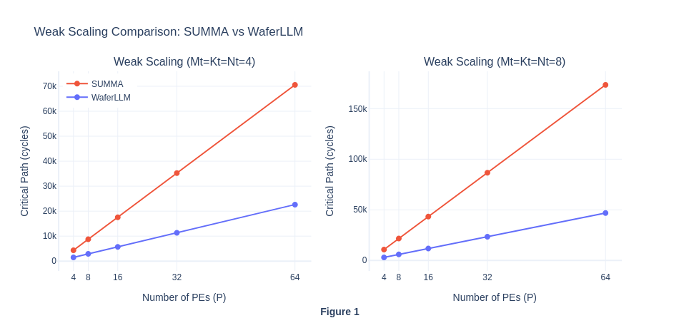
In weak scaling, as the number of PE increases, the amount of work per PE in each step will be kept the same (though each PE will experience more steps because P is larger), and hence the the total workload will increases. For SUMMA, in theory, compute cycle will scale with O(P) and communication latency will scale with O(αP^2). While for MeshGEMM, the compute cycle will scale with O(P) and communication latency will scale with O(α). The weak scaling result reveals two interesting insights. Firstly, similar to our hypothesis, the total number of cycles for WaferLLM’s MeshGEMM scales in O(P) complexity as the communication latency is expected to be constant. However, contrary to our expectation that the total number of cycles for SUMMA will scale in O(αP^2), it actually scales in O(αP). This is contrary to the theoretical properties of SUMMA.
In MeshGEMM, the author noted that cyclic shifting algorithm like Cannon has one main problem of requiring P-1 hops if PE(0) want to communicate with PE(P). The inventors then brilliantly used INTERLEAVE operations to remap logical cores to physical cores. Using their INTERLEAVE algorithms, they managed to reduce the number of hops from logical cores PE(0) to PE(P) to a maximum of 2 hops, given that P>=3. This is done by remapping the logical PE(P) two physical cores away from the physical core PE(0). Thus, by limiting the communication latency to a constant number, it is expected to see MeshGEMM to achieve an O(P) increase in the critical path. As their communication cycle is also lower, they consistently outperform SUMMA in the simulator.
In SUMMA, as shown in our pseudocode above, P steps are required to compute the matrix multiplication result, and for each P, a broadcast will be implemented from one specific row/column to all other columns. The broadcast operation will cause the total number of cycles to scale with P. Intuitively, the higher the number of P, the more hops will be required for the broadcast operations. Hence, in weak scaling, as P increases and the amount of work (tile size) per PE is kept constant, the result was expected to scale in O(αP^2) complexity.
The unexpected result of the O(αP) curve could potentially mean that the simulator gives the same cost for all broadcast operations, treating it as single-step collective and ignores the hop count. Thus, our initial hypothesis is not observed on SUMMA. To validate this idea, more isolation of compute and communication cycles will be needed, we conduct experiment 1.4 to observe their difference.
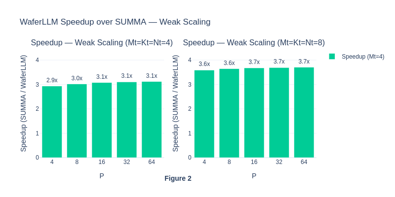 The consistent speed-up of WaferLLM over SUMMA shows the superior performance of WaferLLM’s MeshGEMM over the default SUMMA algorithm.
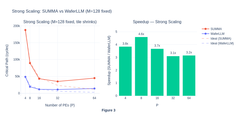 Under strong scaling, when the number of PEs is small, workloads seem to be compute-bound because the matrix size per PE is larger, requiring more computation within each PE. As the number of PE grows, the matrices are split across even smaller partitions on each PE, so the workload per PE becomes lower, total number of critical path cycle decreases and eventually becomes communication-bound. To actually visualise the percentage of compute and communication cycles in each workload run, we will isolate these two types of cycles in Exp 1.4.
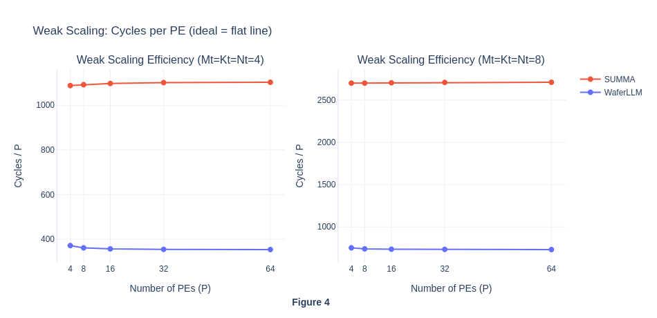 The flat cycles per PE curve further shows that both algorithms appear to exhibit perfect weak scaling and ideal performance, with communication not becoming a bottleneck as PE scales. For MeshGEMM this is expected and seems genuine, because in their paper they claimed INTERLEAVE design bounds hop count to a constant 2 regardless of P, so O(P) scaling is the correct behaviour on real hardware too. For SUMMA however, this suggest a simulator artefact. On real hardware the O(αP) latency per step × P steps = O(αP²) total latency cost would cause the cycles/P ratio to grow with P, not remain flat. This result is abnormal and contrary to SUMMA’s theoretical properties, hence we investigate further in Experiment 1.4.
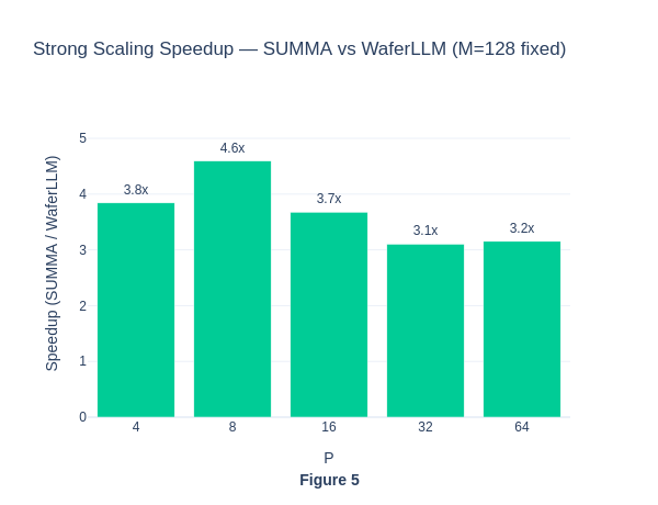 The strong scaling results also show that MeshGEMM consistently performs better than SUMMA.
In this section, MeshGEMM produces a result that is consistent with our hypothesis, showing that a variant of a traditional parallel computing algorithm can be adapted on Cerebras WSE hardware, and still produce a result that is consistent with its original theoretical properties. However, the abnormal SUMMA performance raises questions about the simulator’s correctness. To further analyse why the simulator output O(P) scaling for the SUMMA algorithm, we will decompose the total cycles into computation and communication to identify the bottleneck, and investigate how the incomplete torus topology affects the communication latency.
Exp 1.4: GEMM decomposition (compute vs. comm)
In previous section, the result on critical cycles for each algorithms in matrix multiplication received mixed output:
- MeshGEMM: O(P) total cycles - maches our hypothesis
- SUMMA: O(αP) total cycles - contradicts the theoretical properties where O(αP^2) is expected. This experiment 1.4 is then conducted in an attempt to explain this anomaly, where the Cerebras simulator treats broadcast as single O(α) operation, ignoring hop count routing latency.
To isolate the compute and communciation cycles, we remove the compute task in GEMM (basically was commented out) and leaving only the MPI broadcast operations.
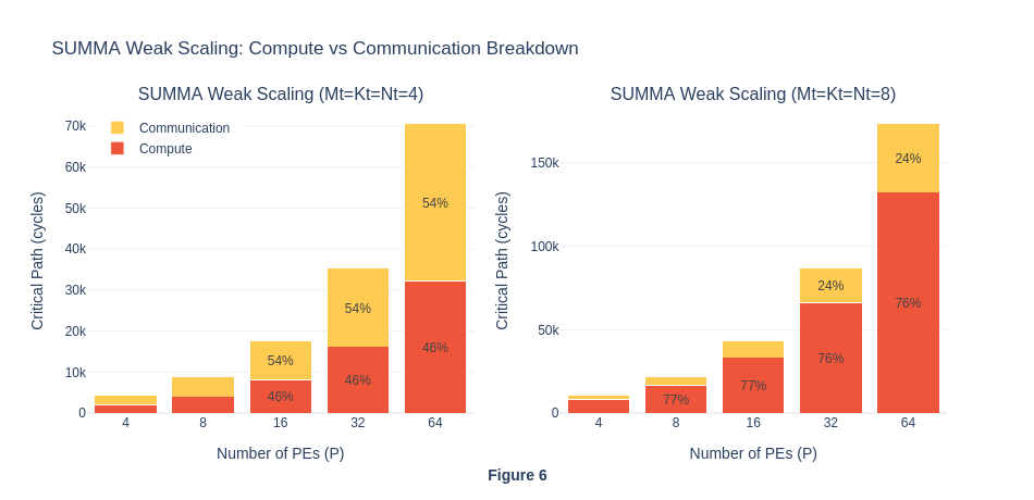 In the graph, we can see that the communication cycles roughly stay the same in percentage across P sizes. On real hardware, a broadcast at P=32 must traverse 31 hops instead of 3, so the per-step cost should be roughly 10× higher at P=32 than at P=4. The simulator shows less than 2% difference. This further suggests that the simulator does not model per-hop routing latency for collective operations such as broadcast, which means that the SUMMA total cycles are underestimated relative to real hardware, where O(αP^2) would be expected.
| Source | SUMMA per step | WaferLLM per step |
|---|---|---|
| Volume | O(P × tile), broadcasts to P−1 peers | Tile transferred point-to-point to 1 neighbour that is 2 hops away |
| Latency (real HW) | O(αP) hops per message | 2 hops (WaferLLM) |
| Total real HW | O(αP²) critical path | O(P) critical path |
| Simulator | O(αP), increase in latency as P scale seems to be ignored, need more experiment to vefify | O(P), relatively faithful |
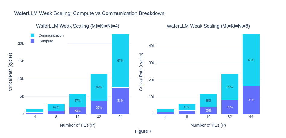
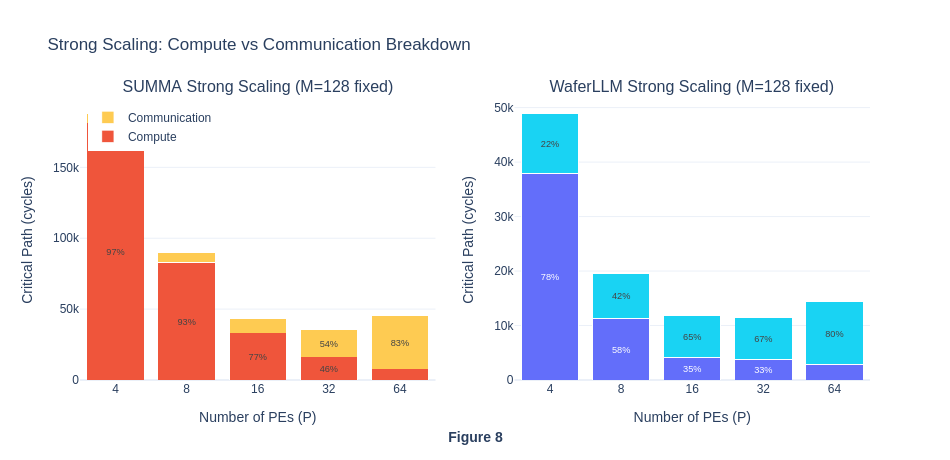 For strong scaling, we can see that compute dominates when P is small, and communication dominates when P is big. This also aligns with our understanding back in Exp 1.3
Experiment 1.4 shows that the simulator underestimates SUMMA’s true communication latency. SUMMA on real hardware would sclae as O(αP^2), not O(αP).WaferLLM’s nearest-neighbour Cannon shifts + INTERLEAVE (2 hop per step regardless of P) would remain O(P) on real hardware, so WaferLLM’s advantage over SUMMA is likely larger in practice than these simulation results suggest.
Summary of Experiment 1
Experiment 1 was designed out of our curiosity about whether traditional parallel computing algorithms will still maintain theoretical properties on actual Cerebras hardware, where the torus topology is incompleted. We hypothesise that MeshGEMM’s O(1) communication would yield O(P) growth in total critical cycles as P grows because their INTERLEAVE operation reduce the boundary wrap cost (originally needed due to lack of torus topology) to 2 hops. This allows the variant of the cannon algorithm to exploit a lower communication volume because it does not use the broadcast primitive every step. And SUMMA O(αP) per step due to the broadcast cost would result in O(αP^2) total cycle growth. In fact, MeshGEMM O(1) communication latency and O(P) growth in total critical cycles were observed in the simulator.
However, the visualisation in Exp 1.3 shows that SUMMA also scaled as O(αP), which contradicts its theoretical properties of O(αP^2) complexity. To further understand this unexpected result, we designed Exp 1.4 to isolate the communication latency cost. In Exp1.4, we found that Cerebras simulator models broadcast as an O(1) operation, ignoring per-hop routing latency, possibly because the tsc clock cycles count is modelled within a single PE, and the simulator model assumes the send and receive data in the broadcast operation among PEs happen instantaneously. Our result further exemplifies this explanation, where the percentage of communication cycles for SUMMA varies by less than 1% across P=4 to P=32, whereas on real hardware, a broadcast at P=32 traverses ~10x more hops than at P=4. This could mean that the simulator underestimates SUMMA’s true cost, and the WaferLLM’s MeshGEMM advantage could be even larger than simulated.
Exp 2: An evaluation on the Cerebras WSE Simulator Validity, based on the anomaly result in Exp 1
To further debug the surprising result of the SUMMA algorithm maintaining an O(αP) critical path cycle on Cerebras hardware. We design another experiment to measure the critical path cycles for data transfer from the leftmost PE to the rightmost PE on the same row. If the simulator correctly models communication latency, the critical path cycles should increase as the processing grid size increases, because the cost of data traversal scales with the number of hops required.
Experimental Design
Independent Variables:
- Processor Grid Size: P=[4,8,16,32,64] for Px1 grid, just a single row to determine the data transfer communication latency.
Dependent Metrics:
- Execution time: Wall-clock cycles (measured by Cerebras SDK)
Baseline and Comparison Conditions:
- Baseline: P=4 which requires 3 hops to send data from leftmost PE to rightmost PE
Controlled Factors:
- Data type: FP16
- Processor topology: Cerebras WSE default with incomplete torus topology
Execution Plan
- Exp 2.1: Implement a point-to-point (P2P) latency benchmark where PE(0) sends 4 FP16 words to PE(P−1) via a hop-by-hop chain, with intermediate PEs performing pure hardware forwarding without any computation involved. record the tsc timestamps at sender and receiver PE for each grid size.
- Exp 2.2: Analyze whether the cycles scale linearly with the number of hop count and check if Cerebras simulator correctly model the communication latency for each hop. Interpret the finding the conclude the limitation of simulator, if any.
Exp 2.1: Implementing P2P latency benchmark where the leftmost PE sends 4 FP16 words to the right most PE.
In the following code, PE(0) sends 4 f16 words to PE(P-1) via a hop-by-hop chain. Both PE(0) and PE(P-1) measure elapsed cycles from startup to receipt. If simulator models per-hop latency: the elapsed cycles will scale with P. Else, the elapsed cycle will stay flat.
layout.csl
// Color map:
//   6  C_CHAIN  (chain message)
//   0-1, 20-23, 27-28, 30  reserved (memcpy)

param P: u16;

const C_CHAIN: color = @get_color(6);

const memcpy = @import_module("<memcpy/get_params>", .{
  .width  = P,
  .height = 1,
});

layout {
  @set_rectangle(P, 1);

  var px: u16 = 0;
  while (px < P) : (px += 1) {
    const memcpy_params = memcpy.get_params(px);
    @set_tile_code(px, 0, "pe.csl", .{
      .memcpy_params = memcpy_params,
      .P     = P,
      .my_px = px,
    });

    if (px == 0) {
      // sender PE injects from RAMP, forward east
      @set_color_config(px, 0, C_CHAIN, .{ .routes = .{ .rx = .{RAMP}, .tx = .{EAST} } });
    } else if (px == P - 1) {
      // receiver PE accepts from west, deliver to RAMP
      @set_color_config(px, 0, C_CHAIN, .{ .routes = .{ .rx = .{WEST}, .tx = .{RAMP} } });
    } else {
      // intermediate PE => pure hardware forwarding, no RAMP involvement
      @set_color_config(px, 0, C_CHAIN, .{ .routes = .{ .rx = .{WEST}, .tx = .{EAST} } });
    }
  }

  @export_name("main",     fn()void);
  @export_name("time_buf", [*]f32, true);
  @export_name("time_ref", [*]f32, true);
  @export_name("recv_buf", [*]f16, true);
}
The following will be the PE code for point-to-point latency test. PE(0) : records tscStart, sends 4 f16 words on C_CHAIN (as defined in the layout code above), records tscEnd. PE(1..P-2) : records timestamps immediately (data passes through in hardware). PE(P-1) : records tscStart, blocks on fabin recv, records tscEnd.
pe.csl
param memcpy_params: comptime_struct;
param P:     u16;
param my_px: u16;

const sys_mod   = @import_module("<memcpy/memcpy>", memcpy_params);
const timestamp = @import_module("<time>");

const EXIT: local_task_id = @get_local_task_id(12);

const C_CHAIN:    color        = @get_color(6);
const chain_out_q              = @get_output_queue(2);
const chain_in_q               = @get_input_queue(2);

// 4 f16 words => keeps alignment safe on WSE-3
var send_buf = [4]f16 { 1.0, 2.0, 3.0, 4.0 };
var recv_buf = [4]f16 { 0.0, 0.0, 0.0, 0.0 };
var ptr_recv_buf: [*]f16 = &recv_buf;

var tscRefBuffer   = @zeros([timestamp.tsc_size_words]u16);
var tscStartBuffer = @zeros([timestamp.tsc_size_words]u16);
var tscEndBuffer   = @zeros([timestamp.tsc_size_words]u16);

var time_buf_f32 = @zeros([3]f32);
var time_ref_f32 = @zeros([2]f32);
var ptr_time_buf: [*]f32 = &time_buf_f32;
var ptr_time_ref: [*]f32 = &time_ref_f32;

fn main() void {
  timestamp.enable_tsc();
  timestamp.get_timestamp(&tscRefBuffer);
  timestamp.get_timestamp(&tscStartBuffer);

  if (my_px == 0) {
    // sender
    const out_dsd = @get_dsd(fabout_dsd, .{
      .fabric_color = C_CHAIN,
      .extent       = 4,
      .output_queue = chain_out_q,
    });
    const buf_dsd = @get_dsd(mem1d_dsd, .{ .tensor_access = |i|{4} -> send_buf[i] });
    @fmovh(out_dsd, buf_dsd);
  } else if (my_px == P - 1) {
    // receiver
    const in_dsd = @get_dsd(fabin_dsd, .{
      .fabric_color = C_CHAIN,
      .extent       = 4,
      .input_queue  = chain_in_q,
    });
    const buf_dsd = @get_dsd(mem1d_dsd, .{ .tensor_access = |i|{4} -> recv_buf[i] });
    @fmovh(buf_dsd, in_dsd);
  }
  // intermediate PE
  @activate(EXIT);
}

fn f_pack_memcpy_timestamps() void {
  var lo_: u16 = 0;
  var hi_: u16 = 0;

  lo_ = tscStartBuffer[0];
  hi_ = tscStartBuffer[1];
  time_buf_f32[0] = @bitcast(f32, (@as(u32, hi_) << @as(u16, 16)) | @as(u32, lo_));

  lo_ = tscStartBuffer[2];
  hi_ = tscEndBuffer[0];
  time_buf_f32[1] = @bitcast(f32, (@as(u32, hi_) << @as(u16, 16)) | @as(u32, lo_));

  lo_ = tscEndBuffer[1];
  hi_ = tscEndBuffer[2];
  time_buf_f32[2] = @bitcast(f32, (@as(u32, hi_) << @as(u16, 16)) | @as(u32, lo_));
}

fn f_pack_ref_timestamps() void {
  var lo_: u16 = 0;
  var hi_: u16 = 0;

  lo_ = tscRefBuffer[0];
  hi_ = tscRefBuffer[1];
  time_ref_f32[0] = @bitcast(f32, (@as(u32, hi_) << @as(u16, 16)) | @as(u32, lo_));

  lo_ = tscRefBuffer[2];
  hi_ = 0;
  time_ref_f32[1] = @bitcast(f32, (@as(u32, hi_) << @as(u16, 16)) | @as(u32, lo_));
}

task f_exit() void {
  timestamp.get_timestamp(&tscEndBuffer);
  f_pack_ref_timestamps();
  f_pack_memcpy_timestamps();
  sys_mod.unblock_cmd_stream();
}

comptime {
  @bind_local_task(f_exit, EXIT);

  if (@is_arch("wse3")) {
    if (my_px == 0) {
      @initialize_queue(chain_out_q, .{ .color = C_CHAIN });
    } else if (my_px == P - 1) {
      @initialize_queue(chain_in_q,  .{ .color = C_CHAIN });
    }
  }

  @export_symbol(ptr_time_buf, "time_buf");
  @export_symbol(ptr_time_ref, "time_ref");
  @export_symbol(ptr_recv_buf, "recv_buf");
  @export_symbol(main);
}
run.py
#!/usr/bin/env cs_python
"""
Analyse point-to-point hop latency in the Cerebras simulator.

Reads timing from PE(P-1) (the last receiver) and reports elapsed cycles
as a function of P.  If the simulator models per-hop routing, elapsed
should grow roughly linearly with P.  If it treats routing as O(1),
elapsed stays flat.

Also reads back recv_buf from PE(P-1) to verify data actually arrived
(not a non-blocking no-op receive).
"""

import argparse
import json
import struct
import numpy as np

from cerebras.sdk.runtime.sdkruntimepybind import SdkRuntime
from cerebras.sdk.runtime.sdkruntimepybind import MemcpyDataType
from cerebras.sdk.runtime.sdkruntimepybind import MemcpyOrder
from cerebras.sdk.sdk_utils import memcpy_view

parser = argparse.ArgumentParser()
parser.add_argument("--name",   help="compiled output directory")
parser.add_argument("--cmaddr", help="IP:port for CS system")
args = parser.parse_args()

with open(f"{args.name}/out.json", encoding="utf-8") as f:
    compile_data = json.load(f)

P = int(compile_data["params"]["P"])

data_dtype = MemcpyDataType.MEMCPY_16BIT
time_dtype = MemcpyDataType.MEMCPY_32BIT

runner = SdkRuntime(args.name, cmaddr=args.cmaddr, suppress_simfab_trace=True)
runner.load()
runner.run()
runner.launch("main", nonblock=False)

w, h = P, 1

# read back recv_buf to confirm data actually arrived
recv_raw = np.zeros(h * w * 4, np.uint32)
runner.memcpy_d2h(recv_raw, runner.get_id("recv_buf"), 0, 0, w, h, 4,
    streaming=False, data_type=data_dtype,
    order=MemcpyOrder.ROW_MAJOR, nonblock=False)

# read timestamps
time_buf_raw = np.zeros(h * w * 3, np.float32)
time_ref_raw = np.zeros(h * w * 2, np.float32)

runner.memcpy_d2h(time_buf_raw, runner.get_id("time_buf"), 0, 0, w, h, 3,
    streaming=False, data_type=time_dtype,
    order=MemcpyOrder.ROW_MAJOR, nonblock=False)
runner.memcpy_d2h(time_ref_raw, runner.get_id("time_ref"), 0, 0, w, h, 2,
    streaming=False, data_type=time_dtype,
    order=MemcpyOrder.ROW_MAJOR, nonblock=False)
runner.stop()

# verify recv_buf at PE(P-1)
recv_f16 = memcpy_view(recv_raw, np.dtype(np.float16)).reshape(h, w, 4)
receiver_buf = recv_f16[0, P-1]   # PE(P-1) recv_buf
expected     = np.array([1.0, 2.0, 3.0, 4.0], dtype=np.float16)
data_arrived = np.allclose(receiver_buf, expected)
print(f"recv_buf at PE({P-1}): {receiver_buf}  (expected {expected}), data_arrived={data_arrived}")
if not data_arrived:
    print("WARNING: recv_buf is all zeros ")

# unpack 48-bit TSC timestamps, in the WaferLLM style to prevent overflow
def to_bits(f):
    return struct.unpack("I", struct.pack("f", float(f)))[0]

def unpack_timestamps(time_buf, time_ref):
    b0, b1, b2 = to_bits(time_buf[0]), to_bits(time_buf[1]), to_bits(time_buf[2])
    start = (b0 & 0xFFFF) | ((b0 >> 16) << 16) | ((b1 & 0xFFFF) << 32)
    end   = (b1 >> 16)    | ((b2 & 0xFFFF) << 16) | ((b2 >> 16) << 32)
    r0, r1 = to_bits(time_ref[0]), to_bits(time_ref[1])
    ref   = (r0 & 0xFFFF) | ((r0 >> 16) << 16) | ((r1 & 0xFFFF) << 32)
    return start, end, ref

time_buf_grid = time_buf_raw.reshape(h, w, 3)
time_ref_grid = time_ref_raw.reshape(h, w, 2)


start_from_ref = np.zeros((h, w), dtype=np.int64)
end_from_ref   = np.zeros((h, w), dtype=np.int64)

for py_i in range(h):
    for px_i in range(w):
        start, end, ref = unpack_timestamps(
            time_buf_grid[py_i, px_i],
            time_ref_grid[py_i, px_i],
        )
        start_from_ref[py_i, px_i] = start - ref  # PE's start offset from ref
        end_from_ref[py_i, px_i]   = end   - ref  # PE's end offset from ref

# PE0 start offset (when it began sending)
sender_offset   = start_from_ref[0, 0]

# PE(P-1) end offset (when it finished receiving)
receiver_offset = end_from_ref[0, P-1]

# end-to-end latency = receiver end - sender start, both relative to their own ref
end_to_end = receiver_offset - sender_offset

hops           = P - 1
cycles_per_hop = end_to_end / hops if hops > 0 else 0

print(f"P={P:3d}  hops={hops:2d}  "
      f"end_to_end_cycles={end_to_end:6,}  "
      f"cycles/hop={cycles_per_hop:.1f}  "
      f"data_arrived={data_arrived}")

import os
csv_file = "p2p_results.csv"
if not os.path.exists(csv_file):
    with open(csv_file, "w") as f:
        f.write("P,hops,end_to_end_cycles,cycles_per_hop,data_arrived\n")
with open(csv_file, "a") as f:
    f.write(f"{P},{hops},{end_to_end},{cycles_per_hop:.1f},{data_arrived}\n")
print(f"Appended to {csv_file}")
run.sh
#!/usr/bin/env bash
# Key question: Does the simulator model per-hop routing latency?
#
# Compiles and runs a 1-row P2P chain for P = 4, 8, 16, 32.
# Check p2p_results.csv afterward:
#   - cycles/hop grows with P  -> simulator models hop latency (O(P) cost)
#   - cycles/hop stays flat    -> simulator treats routing as O(1) bulk
#
# Fabric dims: W = P + 7,  H = 4  (1-row grid with memcpy headroom)

set -e

cd "$(dirname "$0")"

run_p() {
  local P=$1
  local W=$((P + 7))
  echo "=== P=$P ($((P-1)) hops) ==="
  cslc --arch=wse3 layout.csl \
    --fabric-dims=${W},4 --fabric-offsets=4,1 \
    --params=P:${P} \
    --memcpy --channels=1 -o out_p${P}
  cs_python run.py --name out_p${P}
}

run_p 4
run_p 8
run_p 16
run_p 32
run_p 64
run_p 128

echo ""
echo "=== Summary (p2p_results.csv) ==="
cat p2p_results.csv
echo ""
Exp 2.2: Result Interpretation
In the CSV, we notice that the end-to-end cycles are constant as P scales. Specifically, the cycles stay exactly 31 regardless of whether there are 3 hops (P=4) or 127 hops (P=128). This shows that even though the number of hops increases, the cycles stay the same, showing that the simulator models all routing as zero-latency, which is physically impossible on real hardware.
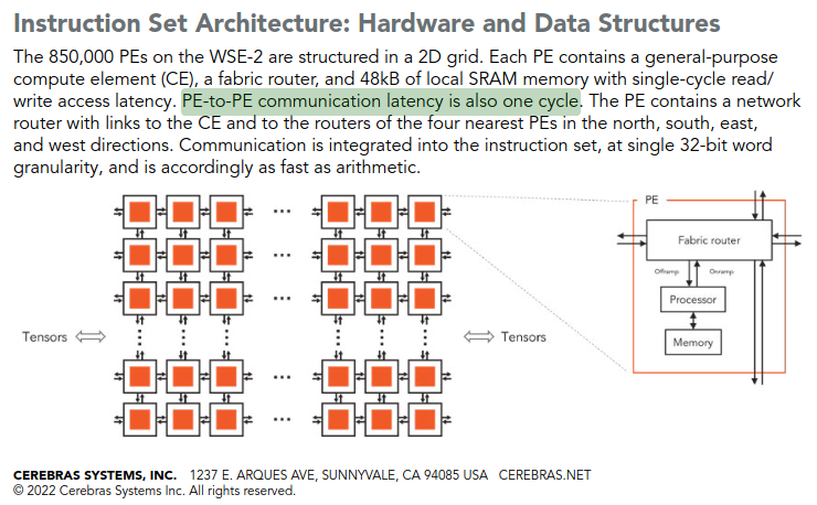
To confirm that the PE-to-PE communication latency actually happens in the hardware, not hidden by advanced pipelining, we also read the Cerebras white paper (shown in the next image) and confirm that at least one cycle is required for PE-to-PE communication latency, hence α is 1. This means that on actual hardware, the communication latency from leftmost PE to rightmost PE for P=128 is 127 cycles, and our Cerebras simulator ignores that.
In conclusion, our receiver cycles remain constant at 31 across P=4 to P=128, despite the number of fabric hops increasing from 3 to 127, confirming that the simulator assigns constant latency to inter-PE routing, which violates the hardware characteristics.
Summary of Experiment 2
Overall, this Exp 2 was motivated by the anomaly observed in Exp 1, and its results have helped us understand why it exists. By confirming that the simulator model’s latency is constant regardless of the size of the processing grid, we now understand why SUMMA exhibited O(αP) scaling rather than the theoretically expected O(αP^2). This finding also reframes how all results in this project should be interpreted. Instead of assuming the simulator faithfully models communication and computation cycles, we can now only say that the simulator correctly models the communication volume and computation cycles, which we have reasonable confidence that computation cycles are faithfully modelled, because the compute kernel operates entirely within local PE memory and does not involve fabric routing. However, the simulator completely ignores the communication latency, which is the number of fabric hops that all the data must traverse.
As a consequence, we know that the SUMMA’s disadvantages are underestimated, and the Cannon’s boundary wrap penalty will be invisible in the critical path cycles. While for WaferLLM, since its INTERLEAVE operations require constant communication latency, which is a maximum of 2 hops, its latency remains O(α) on both the simulator and hardware. This is the only algorithm whose simulator results do not underestimate its true critical path cycles.
All in all, we should interpret the result more carefully by coupling it with the results in this section, bear them in mind, and treat the simulator cycles as a lower bound for the actual hardware implementation.
Experiment 3: Ablation Tests on WaferLLM (Cyclic Shifting + Interleaving)
In WaferLLM, the authors break down MeshGEMM design intuition into 2 major components: Cyclic Shifting and INTERLEAVE operation. We are interested in how each claimed innovation of MeshGEMM adds to the overall end-to-end performance improvement over SUMMA. As established in Experiment 2, the simulator models only model communication volume and not communication latency. This means that the ablation study can isolate the contribution of cyclic shifting, which reduces the communication volume from O(P^2) to O(P), but perhaps cannot directly measure the contribution of INTERLEAVE operations because this innovation mainly tries to reduce communication latency. Nevertheless, we think it is still meaningful to decompose the performance difference in WaferLLM’s MeshGEMM, SUMMA, and Cannon. Because the simulator can still help us monitor the volume difference in terms of communication. We hypothesise that Cannon and MEshGEMM will perform nearly identically in the simulator since both send the same volume per step. And we should probably still see a significant speed up of Cannona nd MeshGEMM compared to SUMMA because of the decrease in communication volume.
In our Cannon implementation, since the torus is absent, the boundary wrap where the first PE must also send data to the last PE, will requires P-1 hops on the fabric. In this section, our main contribution is also writing technically challenging code for Cannon algorithm using the domain specific language CSL. To avoid routing conflict on adjacent PE, we adope a 3-color rotating scheme, 2 for send and receive from adjacent PE, and another dedicated wrap colour for boundary relay.
| Algorithm | Computation per Step | Communication Volume per Step | Critical Path (Real HW) | Critical Path (Simulator) |
|---|---|---|---|---|
| SUMMA | O(P), each PE computes local tile GEMM, over P steps total | O(P × tile), broadcasts one full row/column of P tiles to P−1 peers | O(P) + O(αP^2) | O(P) + O(αP), simulator assigns uniform cost to broadcast regardless of hop count, underestimating communication |
| Cannon (Cyclic Shifting only) | O(P), same local tile GEMM per step as SUMMA, over P steps total | O(tile), shifts one tile point-to-point | O(P) + O(αP^2), boundary wrap incurs P−1 hops per step same as SUMMA | O(P) + O(αP), simulator models boundary wrap as O(1), masking the real hardware penalty |
| WaferLLM (Shifting + Interleaving) | O(P), same local tile GEMM per step as SUMMA, over P steps total | O(tile), shifts one tile point-to-point | O(P) + O(α), INTERLEAVE caps all hops at 2 regardless of P | O(P) + O(α), relatively faithful |
Experiment 3.1: Cannon Algorithm (1-hop Ring Shift)
CANNON():
  px, py = this PE's coordinates
  C_tile = zeros

  // Step 0: compute with the first locally-held tile
  res_tile += X_tile @ W_tile

  // Steps 1 .. P-1: transfer data then compute
  for step = 1 to P-1:
    async send X_tile west;  recv new_X from east
    async send W_tile north; recv new_W from south
    wait for all 4 async ops to complete

    // Swap send/recv pointers so next step sends the freshly received tile.
    X_tile = new_X
    W_tile = new_W

    // Compute phase for new data
    res_tile += X_tile @ W_tile

  return res_tile
Cannon replaces SUMMA’s broadcast with nearest-neighbour ring shifts:
- X tiles: all PEs shift left by 1 each step (data flows WEST)
- W tiles: all PEs shift up by 1 each step (data flows NORTH)
- Boundary wrap: PE(0)→PE(P-1) relay chain going EAST (P-1 fabric hops)
- Pre-skew: done in
run.py— PE(px,py) getsA[py,(px+py)%P]andW[(px+py)%P,px], so that each PE knows which subset of matrices they should compute
| File | Change |
|---|---|
layout.csl |
Add 8 fabric colors: 3 rotating per axis (X_C0/1/2, Y_C0/1/2) + 2 boundary wrap colors (X_wrap, Y_wrap), remove INTERLEAVE color routing |
comm_layout.csl (new) |
3-color rotating scheme: recv_color[i] = C(i%3), send_color[i] = C((i-1)%3), boundary PEs (px=0, px=P-1) use dedicated X_wrap/Y_wrap colors for relay chain |
comm_pe.csl |
Replace two_hop_comm with one_hop_comm: 1-hop parallel ring shift — X tiles shift WEST, W tiles shift NORTH each step |
meshgemm.csl |
Remove INTERLEAVE reverse logic; always shift left/up, double-buffer X_0/X_1, W_0/W_1 with pointer swap after each receive |
run.py |
Add Python-side pre-skew before loading tiles: PE(px,py) receives A[py,(px+py)%P] and W[(px+py)%P,px], sequential tile distribution (core i gets tile i) |
Cannon comm layout: 3-color rotating scheme for 1-hop ring shift.
X left-shift (data flows WEST):
- recv_color[px] =
X_C(px%3)route: EAST->RAMP - send_color[px] =
X_C((px-1)%3)route: RAMP->WEST - Exception px=0: no send WEST; instead sends on X_wrap RAMP->EAST
- Exception px=P-1: no recv from EAST; instead recvs on X_wrap WEST->RAMP
Y up-shift (data flows NORTH):
- recv_color[py] =
Y_C(py%3)route: SOUTH->RAMP - send_color[py] =
Y_C((py-1)%3)route: RAMP->NORTH - Exception py=0: sends on Y_wrap RAMP->SOUTH
- Exception py=P-1: recvs on Y_wrap NORTH->RAMP
Each PE sends on color (px-1)%3 and receives on px%3. This guarantees that no two active sends on the same wire segment share the same color, thus prevent routing conflicts.
If we were only using 2 colors per axis, it would have caused a conflict. With 2 colors alternating,
- PE(even): send=C0, recv=C1 — different
- PE(odd): send=C1, recv=C0 — different
In P=4, PE(1) and PE(3) both receiving on Color C1, when PE(2) sends via C1, PE(1) and PE(3) both will receive and process the data even though PE(1) should the only one receiving it as the data flows uni-directional.
A minimum of 3 colors can solve this issue.
- PE(1) recv: X_C1
- PE(2) recv: X_C2
- PE(3) recv: X_C0
The alternating features through %3 in color assignment can avoid ambiguity in wavelet send and receive.
cannon_comm_layout.csl file will help to create the color parameters helper. In total 8 colors will be assigned, 3 for each axis (X and Y) in the 2D grid, and another 2 for wrap from PE(0) to PE(P), as torus topology is absent. These color assignment will be created during compile time.
cannon_comm_lib/cannon_comm_layout.csl
param P:       i16;
param X_C0:    color;
param X_C1:    color;
param X_C2:    color;
param X_wrap:  color;
param Y_C0:    color;
param Y_C1:    color;
param Y_C2:    color;
param Y_wrap:  color;

fn get_x_color(idx: i16) color {
    if (idx == 0) { return X_C0; }
    else if (idx == 1) { return X_C1; }
    else { return X_C2; }
}

fn get_y_color(idx: i16) color {
    if (idx == 0) { return Y_C0; }
    else if (idx == 1) { return Y_C1; }
    else { return Y_C2; }
}

fn get_params(px: i16, py: i16) comptime_struct {
    // X send/recv
    var x_send_color: color = get_x_color((px - 1 + 3) % 3);
    var x_recv_color: color = get_x_color(px % 3);
    if (px == 0) {
        x_send_color = X_wrap;
        x_recv_color = get_x_color(0);  // C0, receives from px=1
    } else if (px == P-1) {
        x_send_color = get_x_color((px - 1 + 3) % 3);
        x_recv_color = X_wrap;
    }

    // Y send/recv
    var y_send_color: color = get_y_color((py - 1 + 3) % 3);
    var y_recv_color: color = get_y_color(py % 3);
    if (py == 0) {
        y_send_color = Y_wrap;
        y_recv_color = get_y_color(0);
    } else if (py == P-1) {
        y_send_color = get_y_color((py - 1 + 3) % 3);
        y_recv_color = Y_wrap;
    }

    return .{
        .x_send_color = x_send_color,
        .x_recv_color = x_recv_color,
        .y_send_color = y_send_color,
        .y_recv_color = y_recv_color,
    };
}
cannon_layout.csl is the top level file that defines the grid layout. In the code, it will loop over PxP grid to assign the cannon algorithm into each PE. Additionally, it will also set color to wire up each PE routing table.
cannon_layout.csl
// Cannon GEMM layout using collectives_2d for ring shifts.
//
// Color/task ID map:
//  0  c2d_x_color_0
//  1  c2d_x_color_1
//  4  c2d_y_color_0
//  5  c2d_y_color_1
//  8  c2d_x_entrypt_0
//  9  c2d_x_entrypt_1
// 10  c2d_y_entrypt_0
// 11  c2d_y_entrypt_1
// 12  x_finish_id
// 13  y_finish_id
// 14  next_step_id
// 21-30 reserved (memcpy)
param P:  i16;
param Mt: i16;
param Kt: i16;
param Nt: i16;

// 3 rotating colors per axis + 1 wrap color per axis = 8 colors total
const X_C0:   color = @get_color(1);
const X_C1:   color = @get_color(2);
const X_C2:   color = @get_color(3);
const X_wrap: color = @get_color(4);
const Y_C0:   color = @get_color(5);
const Y_C1:   color = @get_color(6);
const Y_C2:   color = @get_color(7);
const Y_wrap: color = @get_color(8);

const memcpy = @import_module("<memcpy/get_params>", .{ .width = P, .height = P });
const comm   = @import_module("cannon_comm_lib/cannon_comm_layout.csl", .{
    .P = P,
    .X_C0 = X_C0, .X_C1 = X_C1, .X_C2 = X_C2, .X_wrap = X_wrap,
    .Y_C0 = Y_C0, .Y_C1 = Y_C1, .Y_C2 = Y_C2, .Y_wrap = Y_wrap,
});

layout {
    @set_rectangle(P, P);

    var px: i16 = 0;
    while (px < P) : (px += 1) {
        const memcpy_params = memcpy.get_params(px);
        var py: i16 = 0;
        while (py < P) : (py += 1) {
            const comm_params = comm.get_params(px, py);
            @set_tile_code(px, py, "cannon_meshgemm.csl", .{
                .memcpy_params = memcpy_params,
                .comm_params   = comm_params,
                .P = P, .Mt = Mt, .Kt = Kt, .Nt = Nt,
            });

            // ---- X routing ----
            if (px == 0) {
                // recv from px=1 on C0 (EAST->RAMP), wrap-send to px=P-1 on X_wrap (RAMP->EAST)
                @set_color_config(px, py, X_C0,   .{ .routes = .{ .rx = .{EAST}, .tx = .{RAMP} } }); //recv from px=1
                @set_color_config(px, py, X_wrap,  .{ .routes = .{ .rx = .{RAMP}, .tx = .{EAST} } }); // send to px=P-1
            } else if (px == P-1) {
                // send to px=P-2 on C((px-1)%3) (RAMP->WEST), recv wrap on X_wrap (WEST->RAMP... wait EAST)
                // X_wrap travels EAST from px=0, arrives from WEST at px=P-1
                @set_color_config(px, py, comm_params.x_send_color, .{ .routes = .{ .rx = .{RAMP}, .tx = .{WEST} } }); // send to px=P-2
                @set_color_config(px, py, X_wrap, .{ .routes = .{ .rx = .{WEST}, .tx = .{RAMP} } }); // recv from px=0
            } else {
                // send WEST on send_color, recv from EAST on recv_color
                // relay wrap (EAST->WEST) and other pass-through colors
                @set_color_config(px, py, comm_params.x_send_color, .{ .routes = .{ .rx = .{RAMP}, .tx = .{WEST} } });
                @set_color_config(px, py, comm_params.x_recv_color, .{ .routes = .{ .rx = .{EAST}, .tx = .{RAMP} } });
                // X_wrap relay EAST->WEST (pass-through, no consume)
                @set_color_config(px, py, X_wrap, .{ .routes = .{ .rx = .{WEST}, .tx = .{EAST} } });
            }

            // ---- Y routing ----
            if (py == 0) {
                @set_color_config(px, py, Y_C0,   .{ .routes = .{ .rx = .{SOUTH}, .tx = .{RAMP} } }); //recv from py=1
                @set_color_config(px, py, Y_wrap,  .{ .routes = .{ .rx = .{RAMP}, .tx = .{SOUTH} } }); //send to py=P-1
            } else if (py == P-1) {
                @set_color_config(px, py, comm_params.y_send_color, .{ .routes = .{ .rx = .{RAMP}, .tx = .{NORTH} } }); //send to py=P-2
                @set_color_config(px, py, Y_wrap, .{ .routes = .{ .rx = .{NORTH}, .tx = .{RAMP} } }); //recv from py=0
            } else {
                @set_color_config(px, py, comm_params.y_send_color, .{ .routes = .{ .rx = .{RAMP}, .tx = .{NORTH} } });
                @set_color_config(px, py, comm_params.y_recv_color, .{ .routes = .{ .rx = .{SOUTH}, .tx = .{RAMP} } });
                @set_color_config(px, py, Y_wrap, .{ .routes = .{ .rx = .{NORTH}, .tx = .{SOUTH} } });
            }
        }
    }

    @export_name("X",                      [*]f16, true);
    @export_name("W",                      [*]f16, true);
    @export_name("res",                    [*]f16, true);
    @export_name("init_task",              fn()void);
    @export_name("meshgemm_entry",         fn()void);
    @export_name("meshgemm_host",          fn(i16, i16)void);
    @export_name("time_memcpy",            [*]f32, true);
    @export_name("time_ref",               [*]f32, true);
    @export_name("f_memcpy_timestamps",    fn()void);
    @export_name("f_reference_timestamps", fn()void);
}
cannon_comm_pe.csl is used to replace the broadcast primitive with 1-hop communication primitive. It launches 4 async @mov16 to move the X-send, X-recv, Y-send, Y-recv simultaneously. After every move, a complete task will be activated when done.
cannon_comm_lib/cannon_comm_pe.csl
// Cannon comm PE: 1-hop ring shift using 3-color rotating scheme.
// Provides one_hop_comm(left_send, right_send, left_recv, right_recv).

param P:   i16;
param Mt:  i16;
param Kt:  i16;
param Nt:  i16;

const _Mt_Kt: i16 = ((Mt * Kt) / 2) * 2;
const _Kt_Nt: i16 = ((Kt * Nt) / 2) * 2;

param x_send_color: color;
param x_recv_color: color;
param y_send_color: color;
param y_recv_color: color;

param x_finish_id: local_task_id;
param y_finish_id: local_task_id;
param x_send_done_id: local_task_id;
param y_send_done_id: local_task_id;

const ut1 = @get_ut_id(1);
const ut2 = @get_ut_id(2);
const ut3 = @get_ut_id(3);
const ut4 = @get_ut_id(4);

const x_send_queue_id = @get_output_queue(2);
const x_recv_queue_id = @get_input_queue(2);
const y_send_queue_id = @get_output_queue(3);
const y_recv_queue_id = @get_input_queue(3);

const dummy = @zeros([1]f16);
var left_matrix_send_dsd  = @get_dsd(mem1d_dsd, .{ .tensor_access = |i|{_Mt_Kt} -> dummy[i] });
var left_matrix_recv_dsd  = @get_dsd(mem1d_dsd, .{ .tensor_access = |i|{_Mt_Kt} -> dummy[i] });
var right_matrix_send_dsd = @get_dsd(mem1d_dsd, .{ .tensor_access = |i|{_Kt_Nt} -> dummy[i] });
var right_matrix_recv_dsd = @get_dsd(mem1d_dsd, .{ .tensor_access = |i|{_Kt_Nt} -> dummy[i] });

comptime {
    @initialize_queue(x_recv_queue_id, .{.color = x_recv_color});
    @initialize_queue(x_send_queue_id, .{.color = x_send_color});
    @initialize_queue(y_recv_queue_id, .{.color = y_recv_color});
    @initialize_queue(y_send_queue_id, .{.color = y_send_color});
}

fn one_hop_comm(left_send: [*]f16, right_send: [*]f16,
                left_recv: [*]f16, right_recv: [*]f16) void {

    left_matrix_send_dsd  = @set_dsd_base_addr(left_matrix_send_dsd,  left_send);
    right_matrix_send_dsd = @set_dsd_base_addr(right_matrix_send_dsd, right_send);
    left_matrix_recv_dsd  = @set_dsd_base_addr(left_matrix_recv_dsd,  left_recv);
    right_matrix_recv_dsd = @set_dsd_base_addr(right_matrix_recv_dsd, right_recv);

    const fab_x_out = @get_dsd(fabout_dsd, .{
        .fabric_color = x_send_color, .extent = _Mt_Kt,
        .output_queue = x_send_queue_id,
        .simd_mode = .{ .simd_64 = true },
    });
    const fab_x_in = @get_dsd(fabin_dsd, .{
        .fabric_color = x_recv_color, .extent = _Mt_Kt,
        .input_queue  = x_recv_queue_id,
        .simd_mode = .{ .simd_64 = true },
    });
    const fab_y_out = @get_dsd(fabout_dsd, .{
        .fabric_color = y_send_color, .extent = _Kt_Nt,
        .output_queue = y_send_queue_id,
        .simd_mode = .{ .simd_64 = true },
    });
    const fab_y_in = @get_dsd(fabin_dsd, .{
        .fabric_color = y_recv_color, .extent = _Kt_Nt,
        .input_queue  = y_recv_queue_id,
        .simd_mode = .{ .simd_64 = true },
    });

    @mov16(left_matrix_recv_dsd,  fab_x_in,  .{.async=true, .activate=x_finish_id, .ut_id=ut2});
    @mov16(fab_x_out, left_matrix_send_dsd,  .{.async=true, .activate=x_send_done_id, .ut_id=ut1});
    @mov16(fab_y_out, right_matrix_send_dsd, .{.async=true, .activate=y_send_done_id, .ut_id=ut3});
    @mov16(right_matrix_recv_dsd, fab_y_in,  .{.async=true, .activate=y_finish_id, .ut_id=ut4});
}
per-pe computation kernel is written here in cannon_meshgemm.csl. The flow is as follows:
- meshgemm_entry(): resets buffers, computes step 0 with home tile (no comm needed), then calls one_hop_comm to start fetching step 1 data
- When all 4 comm tasks fire, comm_done_count reaches 4 -> activates next_step
- next_step -> mm_compute(): swaps send/recv pointers, runs the FMA tile (fmach over Kt rows), increments step
- If step < P: calls one_hop_comm again for the next tile; else: wraps back to meshgemm_entry for the next repeat
- Timestamps captured via TSC for benchmarking The double-buffering (X_0/X_1, W_0/W_1) with pointer swapping means communication and computation can be overlapped.
cannon_meshgemm.csl
// Cannon GEMM PE using collectives_2d for ring communication.
//
// Cannon algorithm:
//   Each step i: PE(px,py) needs the X tile from column (px+step)%P of its row,
//   and the W tile from row (py+step)%P of its column.
//   We implement this as: at step i, the PE whose px==step broadcasts its current
//   X tile along the row, and the PE whose py==step broadcasts its current W tile
//   down the column.  After P steps every PE has seen all P tiles.
//
//   Initial skew (done in run.py):
//     PE(px,py) starts with X tile from col (px+py)%P  (A_blocks[py, (px+py)%P])
//     PE(px,py) starts with W tile from row (px+py)%P  (W_blocks[(px+py)%P, px])
param memcpy_params: comptime_struct;
param comm_params:   comptime_struct;
param P:  i16;
param Mt: i16;
param Kt: i16;
param Nt: i16;


var X_0_tile: [Mt*Kt]f16 = @zeros([Mt*Kt]f16);
var X_1_tile: [Mt*Kt]f16 = @zeros([Mt*Kt]f16);
var ptr_X: [*]f16 = &X_0_tile;

var W_0_tile: [Kt*Nt]f16 = @zeros([Kt*Nt]f16);
var W_1_tile: [Kt*Nt]f16 = @zeros([Kt*Nt]f16);
var ptr_W: [*]f16 = &W_0_tile;

var res_tile: [Mt*Nt]f16 = @zeros([Mt*Nt]f16);
var ptr_res:  [*]f16 = &res_tile;
var res_dsd = @get_dsd(mem1d_dsd, .{ .tensor_access = |i|{Mt*Nt} -> res_tile[i] });

const x_finish_id:  local_task_id = @get_local_task_id(24);
const y_finish_id:  local_task_id = @get_local_task_id(25);
const next_step_id: local_task_id = @get_local_task_id(26);
const x_send_done_id: local_task_id = @get_local_task_id(19);
const y_send_done_id: local_task_id = @get_local_task_id(20);

const sys_mod = @import_module("<memcpy/memcpy>", memcpy_params);
const comm_mod = @import_module("cannon_comm_lib/cannon_comm_pe.csl", @concat_structs(comm_params, .{
    .P = P, .Mt = Mt, .Kt = Kt, .Nt = Nt,
    .x_finish_id    = x_finish_id,
    .y_finish_id    = y_finish_id,
    .x_send_done_id = x_send_done_id,
    .y_send_done_id = y_send_done_id,
}));


var step:               i16 = 0;
var repeat_times:       i16 = 0;
var total_repeat_times: i16 = 1;
var total_warmup_times: i16 = 0;
var comm_done_count:    i16 = 0;

var swap_ptr:    [*]f16 = &X_0_tile;
var ptr_X_send: [*]f16 = &X_0_tile;
var ptr_X_recv: [*]f16 = &X_1_tile;
var ptr_W_send: [*]f16 = &W_0_tile;
var ptr_W_recv: [*]f16 = &W_1_tile;

var out_dsd = @get_dsd(mem1d_dsd, .{ .tensor_access = |i|{Mt} -> res_tile[i] });
var ptr_out: [*]f16 = &res_tile;
var X_dsd   = @get_dsd(mem1d_dsd, .{ .tensor_access = |i|{Mt} -> X_0_tile[i] });
var W_dsd   = @get_dsd(mem1d_dsd, .{ .tensor_access = |i|{Nt} -> W_0_tile[i] });

const out_dest_dsr = @get_dsr(dsr_dest, 1);
const out_src0_dsr = @get_dsr(dsr_src0, 1);
const X_src1_dsr   = @get_dsr(dsr_src1, 1);

const timestamp = @import_module("<time>");
var tscStartBuffer = @zeros([timestamp.tsc_size_words]u16);
var tscEndBuffer   = @zeros([timestamp.tsc_size_words]u16);
var tscRefBuffer   = @zeros([timestamp.tsc_size_words]u16);
var time_buf_f32   = @zeros([3]f32);
var ptr_time_memcpy: [*]f32 = &time_buf_f32;
var time_ref_f32   = @zeros([2]f32);
var ptr_time_ref:   [*]f32 = &time_ref_f32;

fn init_task() void {
    timestamp.enable_tsc();
    sys_mod.unblock_cmd_stream();
}

task x_finish() void {
    comm_done_count += 1;
    if (comm_done_count == 4) { comm_done_count = 0; @activate(next_step_id); }
}
task y_finish() void {
    comm_done_count += 1;
    if (comm_done_count == 4) { comm_done_count = 0; @activate(next_step_id); }
}
task x_send_done() void {
    comm_done_count += 1;
    if (comm_done_count == 4) { comm_done_count = 0; @activate(next_step_id); }
}
task y_send_done() void {
    comm_done_count += 1;
    if (comm_done_count == 4) { comm_done_count = 0; @activate(next_step_id); }
}

task next_step() void {
    mm_compute();
}

fn gemv_static_step_X(curW: f16) void {
    @fmach(out_dest_dsr, out_src0_dsr, X_src1_dsr, curW);
}

fn mm_compute() void {
    // After comm completes: recv buffers have new data. Swap so send=new data.
    swap_ptr = ptr_X_send; ptr_X_send = ptr_X_recv; ptr_X_recv = swap_ptr;
    swap_ptr = ptr_W_send; ptr_W_send = ptr_W_recv; ptr_W_recv = swap_ptr;

    // Compute with current send buffers (freshly received data)
    X_dsd = @set_dsd_base_addr(X_dsd, ptr_X_send);
    W_dsd = @set_dsd_base_addr(W_dsd, ptr_W_send);
    X_dsd = @set_dsd_length(X_dsd, @bitcast(u16, Mt));
    W_dsd = @set_dsd_length(W_dsd, @bitcast(u16, Nt));

    for (@range(i16, Kt)) |k| {
        out_dsd = @set_dsd_base_addr(out_dsd, ptr_out);
        @load_to_dsr(out_dest_dsr, out_dsd, .{ .save_address = true });
        @load_to_dsr(out_src0_dsr, out_dsd, .{ .save_address = true });
        @load_to_dsr(X_src1_dsr,   X_dsd,   .{ .save_address = false });
        @map(gemv_static_step_X, W_dsd);
        X_dsd = @increment_dsd_offset(X_dsd, Mt, f16);
        W_dsd = @increment_dsd_offset(W_dsd, Nt, f16);
    }

    step += 1;

    if (step < P) {
        // Send current data, receive next into recv buffers
        comm_mod.one_hop_comm(ptr_X_send, ptr_W_send, ptr_X_recv, ptr_W_recv);
    } else {
        step = 0;
        meshgemm_entry();
    }
}

fn meshgemm_host(total_warmup_times_: i16, total_repeat_times_: i16) void {
    total_repeat_times = total_repeat_times_;
    total_warmup_times = total_warmup_times_;
    repeat_times = 0;
    step = 0;
    meshgemm_entry();
}

fn meshgemm_entry() void {
    if (repeat_times == total_repeat_times + total_warmup_times) {
        do_exit();
    } else {
        if (repeat_times == total_warmup_times) {
            timestamp.get_timestamp(&tscRefBuffer);
            timestamp.get_timestamp(&tscStartBuffer);
        }
        repeat_times += 1;

        // Home tile in X_0/W_0. First comm sends home tile, recvs neighbor into X_1/W_1.
        ptr_X_send = &X_0_tile;
        ptr_X_recv = &X_1_tile;
        ptr_W_send = &W_0_tile;
        ptr_W_recv = &W_1_tile;

        @fmovh(res_dsd, 0.0);
        ptr_out = &res_tile;
        out_dsd = @set_dsd_base_addr(out_dsd, ptr_out);
        comm_done_count = 0;

        // Step 0: compute with home tile while receiving step 1 data
        // Compute home tile first (no comm needed for step 0)
        X_dsd = @set_dsd_base_addr(X_dsd, ptr_X_send);
        W_dsd = @set_dsd_base_addr(W_dsd, ptr_W_send);
        X_dsd = @set_dsd_length(X_dsd, @bitcast(u16, Mt));
        W_dsd = @set_dsd_length(W_dsd, @bitcast(u16, Nt));

        for (@range(i16, Kt)) |k| {
            out_dsd = @set_dsd_base_addr(out_dsd, ptr_out);
            @load_to_dsr(out_dest_dsr, out_dsd, .{ .save_address = true });
            @load_to_dsr(out_src0_dsr, out_dsd, .{ .save_address = true });
            @load_to_dsr(X_src1_dsr,   X_dsd,   .{ .save_address = false });
            @map(gemv_static_step_X, W_dsd);
            X_dsd = @increment_dsd_offset(X_dsd, Mt, f16);
            W_dsd = @increment_dsd_offset(W_dsd, Nt, f16);
        }

        step = 1;

        if (step < P) {
            // Launch comm for step 1: send home tile, recv into X_1/W_1
            comm_mod.one_hop_comm(ptr_X_send, ptr_W_send, ptr_X_recv, ptr_W_recv);
            // next_step task fires when both x and y comm complete -> calls mm_compute
        } else {
            // P==1 edge case
            step = 0;
            meshgemm_entry();
        }
    }
}

fn do_exit() void {
    timestamp.get_timestamp(&tscEndBuffer);
    timestamp.disable_tsc();
    f_reference_timestamps();
    f_memcpy_timestamps();
    sys_mod.unblock_cmd_stream();
}

fn f_memcpy_timestamps() void {
    var lo_: u16 = 0; var hi_: u16 = 0;
    lo_ = tscStartBuffer[0]; hi_ = tscStartBuffer[1];
    time_buf_f32[0] = @bitcast(f32, (@as(u32,hi_) << @as(u16,16)) | @as(u32, lo_));
    lo_ = tscStartBuffer[2]; hi_ = tscEndBuffer[0];
    time_buf_f32[1] = @bitcast(f32, (@as(u32,hi_) << @as(u16,16)) | @as(u32, lo_));
    lo_ = tscEndBuffer[1];   hi_ = tscEndBuffer[2];
    time_buf_f32[2] = @bitcast(f32, (@as(u32,hi_) << @as(u16,16)) | @as(u32, lo_));
}

fn f_reference_timestamps() void {
    var lo_: u16 = 0; var hi_: u16 = 0;
    lo_ = tscRefBuffer[0]; hi_ = tscRefBuffer[1];
    time_ref_f32[0] = @bitcast(f32, (@as(u32,hi_) << @as(u16,16)) | @as(u32, lo_));
    lo_ = tscRefBuffer[2]; hi_ = 0;
    time_ref_f32[1] = @bitcast(f32, (@as(u32,hi_) << @as(u16,16)) | @as(u32, lo_));
}

comptime {
    @export_symbol(ptr_time_memcpy, "time_memcpy");
    @export_symbol(ptr_time_ref,    "time_ref");
    @export_symbol(ptr_X,   "X");
    @export_symbol(ptr_W,   "W");
    @export_symbol(ptr_res, "res");
    @export_symbol(init_task);
    @export_symbol(meshgemm_entry);
    @export_symbol(meshgemm_host);


    @export_symbol(f_memcpy_timestamps);
    @export_symbol(f_reference_timestamps);

    @bind_local_task(x_finish,  x_finish_id);
    @bind_local_task(y_finish,  y_finish_id);
    @bind_local_task(x_send_done, x_send_done_id);
    @bind_local_task(y_send_done, y_send_done_id);
    @bind_local_task(next_step, next_step_id);
}
cannon_run.py is the python host script file, where the correctness check will be implemented and the critical cycles result will be recorded into csv.
cannon_run.py
#!/usr/bin/env cs_python
# Cannon algorithm run script.
# Pre-skew tiles in Python (no on-chip pre-skew phase):
#   X PE(px,py) <- A block at [row=py, col=(px+py)%P]
#   W PE(px,py) <- B block at [row=(px+py)%P, col=px]

import argparse, json, struct, os
import numpy as np
from cerebras.sdk.sdk_utils import input_array_to_u32, memcpy_view
from cerebras.sdk.runtime.sdkruntimepybind import SdkRuntime, MemcpyDataType, MemcpyOrder

def parse_args():
    parser = argparse.ArgumentParser()
    parser.add_argument("--P",  required=True, type=int)
    parser.add_argument("--M",  required=True, type=int)
    parser.add_argument("--K",  required=True, type=int)
    parser.add_argument("--N",  required=True, type=int)
    parser.add_argument("--out", default="out", help="compiled output dir")
    return parser.parse_args()

def float_to_hex(f):
    return hex(struct.unpack('<I', struct.pack('<f', float(f)))[0])

def make_u48(words):
    return int(words[0]) + (int(words[1]) << 16) + (int(words[2]) << 32)

def main():
    args = parse_args()
    P, M, K, N = args.P, args.M, args.K, args.N
    Mt, Kt, Nt = M // P, K // P, N // P

    np.random.seed(42)
    tensor_X = np.random.rand(M, K).astype(np.float16)
    tensor_W = np.random.rand(K, N).astype(np.float16)

    # ---- Cannon initial tile distribution ----
    # A_blocks[py, px] = A[py*Mt:(py+1)*Mt, px*Kt:(px+1)*Kt]  (Mt x Kt tile)
    A_blocks = tensor_X.reshape(P, Mt, P, Kt).transpose(0, 2, 1, 3)  # (P, P, Mt, Kt)
    # W_blocks[py, px] = W[py*Kt:(py+1)*Kt, px*Nt:(px+1)*Nt]  (Kt x Nt tile)
    W_blocks = tensor_W.reshape(P, Kt, P, Nt).transpose(0, 2, 1, 3)  # (P, P, Kt, Nt)

    # Cannon skew: PE(px,py) gets A_blocks[py, (px+py)%P] and W_blocks[(px+py)%P, px]
    X_skewed = np.zeros((P, P, Mt, Kt), dtype=np.float16)
    W_skewed = np.zeros((P, P, Kt, Nt), dtype=np.float16)
    for py_i in range(P):
        for px_i in range(P):
            src = (px_i + py_i) % P
            X_skewed[py_i, px_i] = A_blocks[py_i, src]
            W_skewed[py_i, px_i] = W_blocks[src,   px_i]

    # Pack X as (Kt, Mt) per tile for col-major CSL DSD access
    X3 = X_skewed.transpose(0, 1, 3, 2).reshape(P, P, Mt * Kt)  # (P,P,Kt,Mt) -> flat
    X_u32 = input_array_to_u32(X3.ravel(), 1, 1)

    # Pack W as (Kt, Nt) per tile (row-major, matches CSL W_dsd stride)
    W3 = W_skewed.reshape(P, P, Kt * Nt)
    W_u32 = input_array_to_u32(W3.ravel(), 1, 1)

    io_dtype = MemcpyDataType.MEMCPY_16BIT
    runner = SdkRuntime(args.out, suppress_simfab_trace=True)
    runner.load()
    runner.run()

    sym_X   = runner.get_id("X")
    sym_W   = runner.get_id("W")
    sym_res = runner.get_id("res")
    sym_time_memcpy = runner.get_id("time_memcpy")
    sym_time_ref    = runner.get_id("time_ref")

    runner.memcpy_h2d(sym_X, X_u32, 0, 0, P, P, Mt*Kt,
        streaming=False, data_type=io_dtype, order=MemcpyOrder.ROW_MAJOR, nonblock=False)
    runner.memcpy_h2d(sym_W, W_u32, 0, 0, P, P, Kt*Nt,
        streaming=False, data_type=io_dtype, order=MemcpyOrder.ROW_MAJOR, nonblock=False)

    # Correctness run (1 repeat, no warmup)
    runner.launch('init_task', nonblock=False)
    runner.launch('meshgemm_host', np.int16(0), np.int16(1), nonblock=False)

    res_u32 = np.zeros(P*P*Mt*Nt, dtype=np.uint32)
    runner.memcpy_d2h(res_u32, sym_res, 0, 0, P, P, Mt*Nt,
        streaming=False, data_type=io_dtype, order=MemcpyOrder.ROW_MAJOR, nonblock=False)
    res_fp16 = memcpy_view(res_u32, np.dtype(np.float16))
    res3 = res_fp16.reshape(P, P, Nt, Mt)
    res  = res3.transpose(0, 3, 1, 2).reshape(M, N)
    np.testing.assert_allclose(np.matmul(tensor_X, tensor_W), res, rtol=1e-1, atol=1e-1)
    print("Correctness check PASSED")

    # Timed run (1 warmup + 5 repeats)
    runner.launch('init_task', nonblock=False)
    total_warmup, total_repeat = 0, 1
    runner.launch('meshgemm_host', np.int16(total_warmup), np.int16(total_repeat), nonblock=False)

    time_memcpy_raw = np.zeros(P*P*3, dtype=np.float32)
    time_ref_raw    = np.zeros(P*P*2, dtype=np.float32)
    runner.memcpy_d2h(time_memcpy_raw, sym_time_memcpy, 0, 0, P, P, 3,
        streaming=False, data_type=MemcpyDataType.MEMCPY_32BIT,
        order=MemcpyOrder.ROW_MAJOR, nonblock=False)
    runner.memcpy_d2h(time_ref_raw, sym_time_ref, 0, 0, P, P, 2,
        streaming=False, data_type=MemcpyDataType.MEMCPY_32BIT,
        order=MemcpyOrder.ROW_MAJOR, nonblock=False)
    runner.stop()

    # Unpack timestamps
    time_memcpy_hwl = time_memcpy_raw.reshape(P, P, 3)
    time_ref_hwl    = time_ref_raw.reshape(P, P, 2)

    time_start = np.zeros((P, P), dtype=np.int64)
    time_end   = np.zeros((P, P), dtype=np.int64)
    for h in range(P):
        for w in range(P):
            t0 = int(float_to_hex(time_memcpy_hwl[h,w,0]), 16)
            t1 = int(float_to_hex(time_memcpy_hwl[h,w,1]), 16)
            t2 = int(float_to_hex(time_memcpy_hwl[h,w,2]), 16)
            time_start[h,w] = make_u48([t0 & 0xffff, (t0>>16) & 0xffff, t1 & 0xffff])
            time_end[h,w]   = make_u48([(t1>>16) & 0xffff, t2 & 0xffff, (t2>>16) & 0xffff])

    time_ref = np.zeros((P, P), dtype=np.int64)
    for h in range(P):
        for w in range(P):
            r0 = int(float_to_hex(time_ref_hwl[h,w,0]), 16)
            r1 = int(float_to_hex(time_ref_hwl[h,w,1]), 16)
            time_ref[h,w] = make_u48([r0 & 0xffff, (r0>>16) & 0xffff, r1 & 0xffff])
            time_ref[h,w] -= (w + h)  # skew correction

    time_start -= time_ref
    time_end   -= time_ref

    critical_path = int((time_end.max() - time_start.min()) / total_repeat)
    mean_cycles   = float(np.mean(time_end - time_start)) / total_repeat

    print(f"P={P} M={M} K={K} N={N}  Mt={Mt} Kt={Kt} Nt={Nt}")
    print(f"Critical path: {critical_path:,}  Mean: {mean_cycles:,.1f}")

    csv_file = "scaling_results.csv"
    if not os.path.exists(csv_file):
        with open(csv_file, "w") as f:
            f.write("algorithm,P,M,K,N,Mt,Kt,Nt,critical_path,mean_cycles,repeat_times\n")
    with open(csv_file, "a") as f:
        f.write(f"cannon,{P},{M},{K},{N},{Mt},{Kt},{Nt},{critical_path},{mean_cycles:.1f},{total_repeat}\n")
    print(f"Appended to {csv_file}")

if __name__ == "__main__":
    main()
benchmark driver, bash script file
cannon_bench.sh
#!/usr/bin/env bash
set -e

TILE=8  # Mt=Kt=Nt=TILE, M=K=N=P*TILE (weak scaling)

echo "=== Cannon Weak Scaling, TIle=8 ==="
for P in 4 8 16 32 64; do
    M=$(($P * $TILE))
    echo "--- P=$P M=$M ---"
    OUT="out"
    cslc --arch=wse3 cannon_layout.csl \
        --params=P:${P},Mt:${TILE},Kt:${TILE},Nt:${TILE} \
        --fabric-dims=$((P+7)),$((P+2)) \
        --fabric-offsets=4,1 \
        --memcpy --channels=1 -o $OUT
    cs_python cannon_run.py --P $P --M $M --K $M --N $M --out $OUT
done

TILE=4  # Mt=Kt=Nt=TILE, M=K=N=P*TILE (weak scaling)

echo "=== Cannon Weak Scaling, Tile=4 ==="
for P in 4 8 16 32 64; do
    M=$(($P * $TILE))
    echo "--- P=$P M=$M ---"
    OUT="out"
    cslc --arch=wse3 cannon_layout.csl \
        --params=P:${P},Mt:${TILE},Kt:${TILE},Nt:${TILE} \
        --fabric-dims=$((P+7)),$((P+2)) \
        --fabric-offsets=4,1 \
        --memcpy --channels=1 -o $OUT
    cs_python cannon_run.py --P $P --M $M --K $M --N $M --out $OUT
done

echo ""
echo "=== Cannon Strong Scaling (M=K=N=128) ==="
M=128; K=128; N=128
for P in 4 8 16 32 64; do
    Mt=$(($M / $P)); Kt=$(($K / $P)); Nt=$(($N / $P))
    echo "--- P=$P Mt=$Mt ---"
    OUT="out"
    cslc --arch=wse3 cannon_layout.csl \
        --params=P:${P},Mt:${Mt},Kt:${Kt},Nt:${Nt} \
        --fabric-dims=$((P+7)),$((P+2)) \
        --fabric-offsets=4,1 \
        --memcpy --channels=1 -o $OUT
    cs_python cannon_run.py --P $P --M $M --K $K --N $N --out $OUT
done
Section 3.2: Result Analysis (SUMMA, Cannon and WaferLLM’s MeshGEMM)
In our implementation, this ablation study creates 3 data points:
SUMMA -> Cannon (Claimed Innovation 1: Cyclic Shifting) -> WaferLLM MeshGEMM (Both Claimed Innovation 1+2: Cyclic Shifting + INTERLEAVE)
Before interpreting any figure, we must restate the key caveat established in Exp 2, where the Simulator models all fabric operations, inlcuding broadcast and multi-hop ring relay as O(1) cost regardless of hop count. This means that the simulator will underestimates any algorithm whose critical path bottleneck is a long distance communication with multiple hops. Specifically:
- SUMMA’s broadcast is underestimated (real cost: O(αP) hops per step)
- Cannon’s boundary wrap is also underestimated (real cost: P−1 hops per step going EAST from PE(0) to PE(P), in the absent of torus topology)
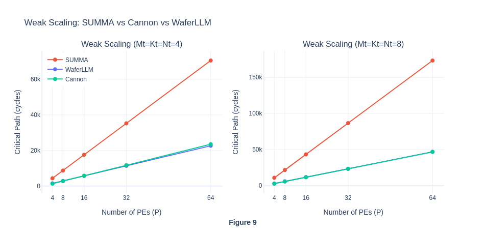 In Figure 9, we found that our Cannon implementation has a very similar trend with MeshGEMM in WaferLLM, with both line almost overlap entirely with each other. In is also consistent with our hypothesis where the result of Cannon and MeshGEMM will be similar because they have similar communication volume. Regardless of the sizes of P, since the hop-count latency is not modelled in the simulator, the Cannon’s O(P) bounadry wrap cost is also invisible. Note that α is establish to be 1 in Exp 2, hence the total critical path cycles for Cannon and WaferLLM are correctly modelled as O(P) in the simulator.
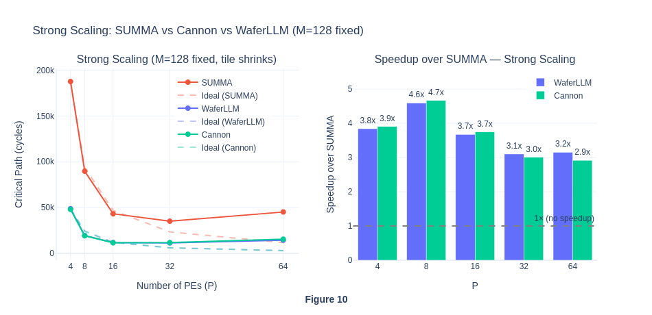 In strong scaling, we could observe a minor ablation signal when looking into Cannon and WaferLLM MeshGEMM. At P < 16, Cannon is marginally faster than WaferLLM, while at P > 16, WaferLLM is marginally faster. However, given that the simulator cannot model hop latency, this small difference may reflect minor overhead differences in the two CSL implementations rather than a true algorithmic signal. On real hardware where each hop carries an actual latency cost, the divergence is expected to be much steeper.
Experiment 3.3: Cannon (Isolating Compute and Comm Ops)
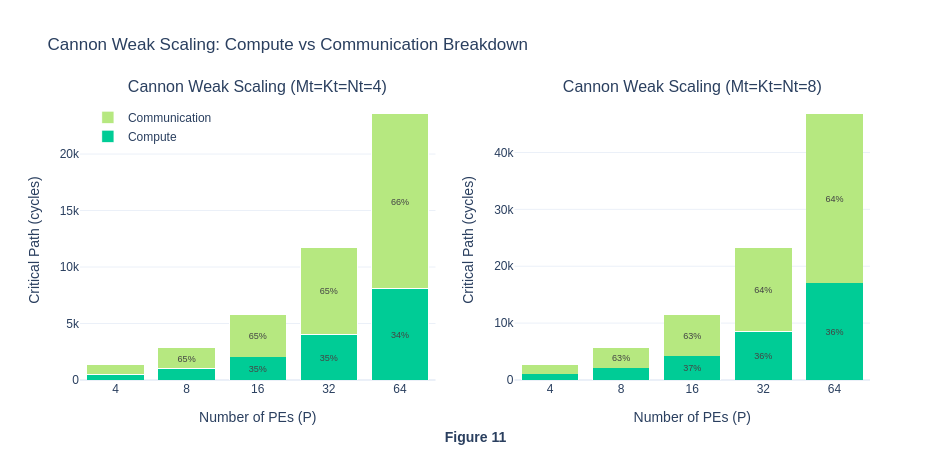 Under weak scaling regime, Cannon’s communication percentage stays flat across all P values, this is the same pattern found in SUMMA Exp1.4 breakdown, and is not suppose to happen in real hardware due to communication latency. This is further confirming that the O(P) wrap cost in hop latency is ignored by the simulator.
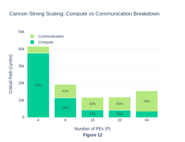 In cannon strong scaling, the percentage of communication cycles increases as P increases, which is consistent with our previous findings where communication cycles increase as tile size decreases and the number of PE increases.
Summary of Experiment 3
Our initial motivation for this experiment is to quantify the contribution of each claimed innovation in MeshGEMM to the overall end-to-end performance improvement over SUMMA. To investigate and isolate the impact of cyclic shifting and INTERLEAVE operations, we adopt the Cannon algorithm and implement it using Cerebras CSL as an intermediate baseline between SUMMA and MeshGEMM. One key implementation challenge is that Cerebras uses a 2D mesh rather than a torus topology that is assumed by the traditional Cannon algorithm. To mitigate this, we added 2 more colour channels in Cerebras layout, so that we can relay the data from PE(0) to PE(P-1) through another route. To avoid channel conflict in send and receive protocols, we also use a 3-colour rotating scheme in our design. Overall, we successfully implemented Cannon’s algorithm on the Cerebras WSE-3 and verified its correctness using numpy.
In the simulator, we found that the cyclic shifting alone (cannon algorithm) accounts for the majority of the speed up compared to SUMMA across all P values. This is because Cannon shift tiles point-to-point to immediate neighbours, instead of using broadcast operations like SUMMA, thus massively reduces the communication volume. The INTERLEAVE operations, which distinguish Cannon from MeshGEMM, contribute negligible benefit to the overall critical cycles in the simulator. This is consistent with our earlier observation where the simulator model boundary wrap as O(1) cost (31 hops), which masks the benefit of INTERLEAVE operation which bounds the maximum number of hops to 2.
On real hardware, we would expect a different picture. Without INETERLEAVE, Cannon’s boundary wrap will bound the critical path cycles for communication to O(αP²). MeshGEMM INTERLEAVE will bound the communication to a maximum of 2 hops, and reduce the communication cycles to a constant O(α) regardless of P. As a result, we expect the gap between Cannon and MeshGEMM to be significantly widened as P increases, and the MeshGEMM advantage over both SUMMA and Cannon will be larger than what the simulator currently suggests.
Experiment 4: High Hidden Dimension — K-Sweep Comparison (Exploratory)
In experiment 4, we are curious about the behaviour of SUMMA, Cannon and MeshGEMM on real-word language model workload. In practice, rectangular matrices with high K values are always involved:
- M: sequence length
- N: output feature dimension (affected by the number of attention heads, intermediate MLP size, etc)
- K: input feature dimension (hidden size and the internal vector representation of a word / token, typically a bigger number than M and N).
In here, we wonder how would the performance be affected if the K is significantly larger than M and N in the computation. Additionally, does the relative ranking of algorithms change as K grows? To investigate into this issue, we fix P=8, M=N=64 and varying K ∈ {32, 64, 128, 256, 512} (i.e., Kt ∈ {4, 8, 16, 32, 64}).
In our experiment, we know that all three algorithm compute the same data volume per step, which is Mt x Kt x Nt. However, the key difference lies in how the data is communicated among PEs. For each step, tiles of size Mt x Kt and Kt x Nt are communicated, but how does the communication volume scales with K?
| Algorithm | Total volume received per PE per step | Communication pattern | Volume |
|---|---|---|---|
| SUMMA | (Mt×Kt + Kt×Nt) | Broadcast Mt×Kt to P−1 peers per row, Broadcast Kt x Nt to P-1 peers per column | ∝ K |
| Cannon | (Mt×Kt + Kt×Nt) | Ring shift: 1 sender -> 1 receiver, but boundary wrap = P−1 hops | ∝ K |
| WaferLLM | (Mt×Kt + Kt×Nt) | INTERLEAVE shift: 1 sender -> 1 receiver, max 2 hops always | ∝ K |
From our understanding, the key difference is not volume but hop count. Since the simulator models all routing as O(1) latency regardless of hop count, we don’t think that the simulator can capture this difference, and we expect all threee algorithm to scale linearly with K in the simulator.
Data sources:
- SUMMA:
exp1/summa/scaling_results.csv - WaferLLM:
WaferLLM/MeshGEMM/WSE-3/scaling_results.csv - Cannon:
exp3/cannon/scaling_results.csv
Experiment 4.1: Scaling K in all 3 algorithms (SUMMA, Cannon and MeshGEMM from WaferLLM)
rectangular.sh
#!/usr/bin/env bash
set -e

echo "=== P=8 ==="
echo "=== Kt=4 ==="
cslc --arch=wse3 ./layout.csl --fabric-dims=15,11 --fabric-offsets=4,1 \
--params=P:8,Mt:8,Kt:4,Nt:8 \
--memcpy --channels=1 -o out_p4
cs_python run.py --name out_p4

echo "=== Kt=8 ==="
cslc --arch=wse3 ./layout.csl --fabric-dims=15,11 --fabric-offsets=4,1 \
--params=P:8,Mt:8,Kt:8,Nt:8 \
--memcpy --channels=1 -o out_p8
cs_python run.py --name out_p8

echo "=== Kt=16 ==="
cslc --arch=wse3 ./layout.csl --fabric-dims=15,11 --fabric-offsets=4,1 \
--params=P:8,Mt:8,Kt:16,Nt:8 \
--memcpy --channels=1 -o out_p16
cs_python run.py --name out_p16

echo "=== Kt=32 ==="
cslc --arch=wse3 ./layout.csl --fabric-dims=15,11 --fabric-offsets=4,1 \
--params=P:8,Mt:8,Kt:32,Nt:8 \
--memcpy --channels=1 -o out_p32
cs_python run.py --name out_p32

echo "=== Kt=64 ==="
cslc --arch=wse3 ./layout.csl --fabric-dims=15,11 --fabric-offsets=4,1 \
--params=P:8,Mt:8,Kt:64,Nt:8 \
--memcpy --channels=1 -o out_p64
cs_python run.py --name out_p64

echo "=== P=8 ==="
echo "=== Kt=4 ==="
cslc --arch=wse3 ./layout.csl --fabric-dims=15,11 --fabric-offsets=4,1 \
--params=P:8,Mt:4,Kt:4,Nt:4 \
--memcpy --channels=1 -o out_p4
cs_python run.py --name out_p4

echo "=== Kt=8 ==="
cslc --arch=wse3 ./layout.csl --fabric-dims=15,11 --fabric-offsets=4,1 \
--params=P:8,Mt:4,Kt:8,Nt:4 \
--memcpy --channels=1 -o out_p8
cs_python run.py --name out_p8

echo "=== Kt=16 ==="
cslc --arch=wse3 ./layout.csl --fabric-dims=15,11 --fabric-offsets=4,1 \
--params=P:8,Mt:4,Kt:16,Nt:4 \
--memcpy --channels=1 -o out_p16
cs_python run.py --name out_p16

echo "=== Kt=32 ==="
cslc --arch=wse3 ./layout.csl --fabric-dims=15,11 --fabric-offsets=4,1 \
--params=P:8,Mt:4,Kt:32,Nt:4 \
--memcpy --channels=1 -o out_p32
cs_python run.py --name out_p32

echo "=== Kt=64 ==="
cslc --arch=wse3 ./layout.csl --fabric-dims=15,11 --fabric-offsets=4,1 \
--params=P:8,Mt:4,Kt:64,Nt:4 \
--memcpy --channels=1 -o out_p64
cs_python run.py --name out_p64
l46_bench_rectangular.sh
#!/usr/bin/env bash
set -e

P=8
M=64
N=64

for K in 32 64 128 256 512; do
    Mt=$(($M / $P))
    Kt=$(($K / $P))
    Nt=$(($N / $P))
    fabric_w=$(($P + 7))
    fabric_h=$(($P + 4))
    echo "=== P=$P, M=$M, K=$K, N=$N, Mt=$Mt, Kt=$Kt, Nt=$Nt ==="
    cslc --arch=wse3 ./src/layout.csl \
        --fabric-dims="$fabric_w","$fabric_h" \
        --fabric-offsets=4,1 \
        --params=P:"$P",Mt:"$Mt",Kt:"$Kt",Nt:"$Nt" \
        -o out --memcpy --channels 1
    cs_python ./launch_sim.py --P "$P" --M "$M" --K "$K" --N "$N"
done


P=8
M=32
N=32

for K in 32 64 128 256 512; do
    Mt=$(($M / $P))
    Kt=$(($K / $P))
    Nt=$(($N / $P))
    fabric_w=$(($P + 7))
    fabric_h=$(($P + 4))
    echo "=== P=$P, M=$M, K=$K, N=$N, Mt=$Mt, Kt=$Kt, Nt=$Nt ==="
    cslc --arch=wse3 ./src/layout.csl \
        --fabric-dims="$fabric_w","$fabric_h" \
        --fabric-offsets=4,1 \
        --params=P:"$P",Mt:"$Mt",Kt:"$Kt",Nt:"$Nt" \
        -o out --memcpy --channels 1
    cs_python ./launch_sim.py --P "$P" --M "$M" --K "$K" --N "$N"
done
cannon_k_sweep.sh
#!/usr/bin/env bash
set -e
# K-sweep: P=8, M=N=64, K in {64, 128, 256, 512}
P=8; M=64; N=64
for K in 32 64 128 256 512; do
    Mt=$(($M / $P)); Kt=$(($K / $P)); Nt=$(($N / $P))
    echo "--- K=$K Kt=$Kt ---"
    OUT="out_ksweep_K${K}"
    cslc --arch=wse3 cannon_layout.csl \
        --params=P:${P},Mt:${Mt},Kt:${Kt},Nt:${Nt} \
        --fabric-dims=$((P+7)),$((P+2)) \
        --fabric-offsets=4,1 \
        --memcpy --channels=1 -o $OUT
    cs_python cannon_run.py --P $P --M $M --K $K --N $N --out $OUT
done

P=8; M=32; N=32
for K in 32 64 128 256 512; do
    Mt=$(($M / $P)); Kt=$(($K / $P)); Nt=$(($N / $P))
    echo "--- K=$K Kt=$Kt ---"
    OUT="out_ksweep_K${K}"
    cslc --arch=wse3 cannon_layout.csl \
        --params=P:${P},Mt:${Mt},Kt:${Kt},Nt:${Nt} \
        --fabric-dims=$((P+7)),$((P+2)) \
        --fabric-offsets=4,1 \
        --memcpy --channels=1 -o $OUT
    cs_python cannon_run.py --P $P --M $M --K $K --N $N --out $OUT
done
Section 4.2: Result Analysis
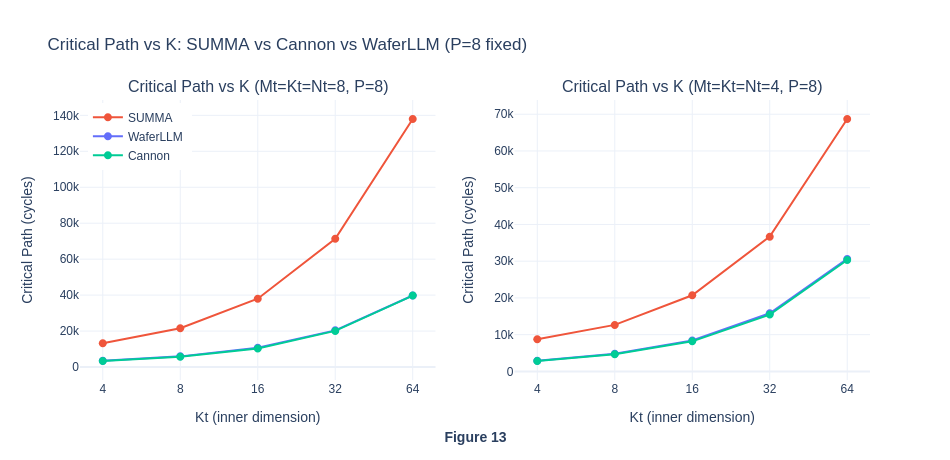 Based on the simulator result, all three algorithm grows roughly the same at linear speed with K but with different rates. Both Cannon and WaferLLM maintain a consistent 3.5-3.9x speed up over SUMMA across all K values.
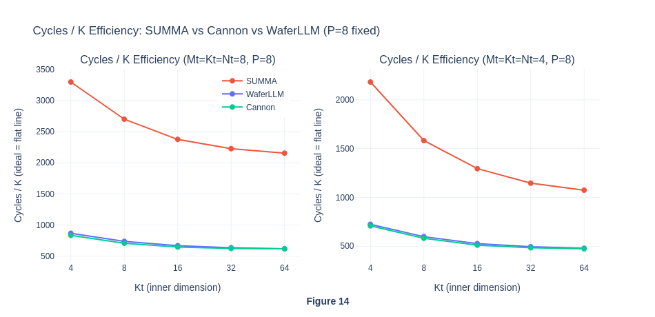 In the graphs above, dividing the critical path by Kt reveals how efficiently each algorithm utilises the K dimension. A perfect linear scaling would show a flat line. In our result, all three curves decrease and flatten as Kt grows. The key observation is that Cannon and WaferLLM converge to about the same cycles/Kt at large K, while SUMMA remains 3.5x above them even at Kt=64.
As Cannon and WaferLLM would retain an advantage at large K on real hardware due to simulator artefact, the convergence seen in Figure 14 should be interpreted as a lower bound on WaferLLM’s and Cannon’s advantage over SUMMA.
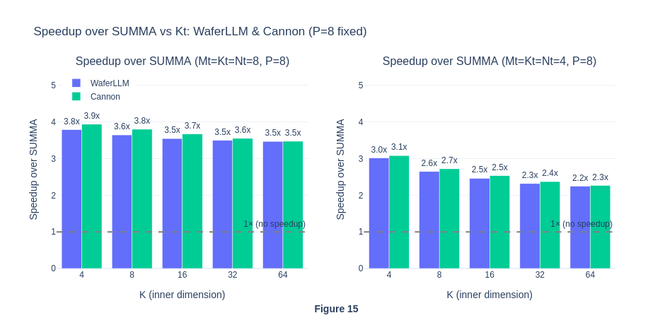 From the graphs, we observe the speed up decreases and plateau as K grows. This is because SUMMA amortises its constant broadcast overhead as K increases, thus slightly close the gap in speed up graph. On real hardware, SUMMA broadcast cost traverse O(αP) hops per step, a constant hop penalty that doesnot amortise with K. The simulator didn’t account for this, thus making SUMMA looks relatively better when K becomes larger. On real hardware, the speed up of Cannon and WaferLLM over SUMMA would be expected to be larger, and would not decline with K to the same degree.
Summary of Experiment 4
Overall, experiment 4 answered our 2 questions, but with caveats. Firstly, all the algorithms scale O(K) with K. Secondly, the relative ranking does not change. SUMMA remains 3.5-3.9x slower than both Cannon and WaferLLM across all K values, showing the advantage of cyclic-shift algorithms on Cerebras hardware. Cannon and Wafer LLM have similar performance at large K. However, this convergence is an artefact of the simulator’s O(1) hop model. On real hardware, Cannon’s O(αP) boundary wrap penalty is a constant per-step cost independent of K, so the WaferLLM would retain an advantage even at very large K.
Summary of L46 Project
Overall, this project is motivated by several factors: (1) Cerebras WSE engine was mentioned in L46 lecture, (2) Spatial Architecture was also featured in Vivienne Sze’s review on efficient processing of DNN, (3) my own curiosity in learning to program in Cerebras CSL, (4) WaferLLM as an interesting paper published at OSDI.
This project starts with the idea of reproducing the WaferLLM MeshGEMM algorithm results, then evolves into adapting the SUMMA algorithm to FP16, followed by investigating the simulator artefact, adapting traditional parallel computing algorithms like Cannon to make them feasible on Cerebras hardware, even without a torus topology, and lastly all three algorithms under realistic LLM matrix shapes. For Experiment 1, we reproduced MeshGEMM’s strong and weak scaling results against SUMMA. We show that MeshGEMM delivers O(P) weak scaling as claimed, but were surprised by SUMMA, which contradicts its theoretical O(αP^2) complexity. Experiment 1.4 first revealed the cause, where SUMMA’s communication percentage stays constant across all P values, whereas on real hardware it should grow as the broadcast traverses more hops. Then, for Experiment 2, we design another simpler experiment to isolate the P2P communication latency effect, to identify the root cause of the anomaly result, and conclude the simulator artefact. Eventually, Experiment 2 found that the simulator assigns exactly the same cycle count regardless of whether data travels 3 or 127 hops. Together, these establish that the simulator models all routing as O(1), meaning SUMMA’s true cost on real hardware is substantially underestimated. For Experiment 3, we show that cyclic shifting alone captured most of the performance gain over SUMMA, while MeshGEMM and Cannon have similar performance due to a similar communication volume under the cyclic shifting paradigm. On real hardware, Cannon’s O(αP) boundary wrap penalty would cause it to degrade relative to MeshGEMM at large P. In Experiment 4, we attempt to replicate realistic matrix sizes on the simulator and confirm that the relative ranking of the algorithms remains stable as K scales.
Throughout the study, the central limitation is the simulator’s O(1) hop model, which means all observed differences between algorithms reflect communication volume rather than communication latency. On real hardware, theoretically speaking, SUMMA would scale O(αP^2) in weak scaling, and Cannon would degrade relative to WaferLLM at large P. WaferLLM’s INTERLEAVE innovation that helps to bound all hops to a constant 2, regardless of P, is probably the only design that transfers faithful simulator results onto hardware. The simulation results, therefore, represent a lower bound on WaferLLM’s true advantage over both SUMMA and Cannon.